DISASSEMBLY OF BASIC ENGINE
5-12
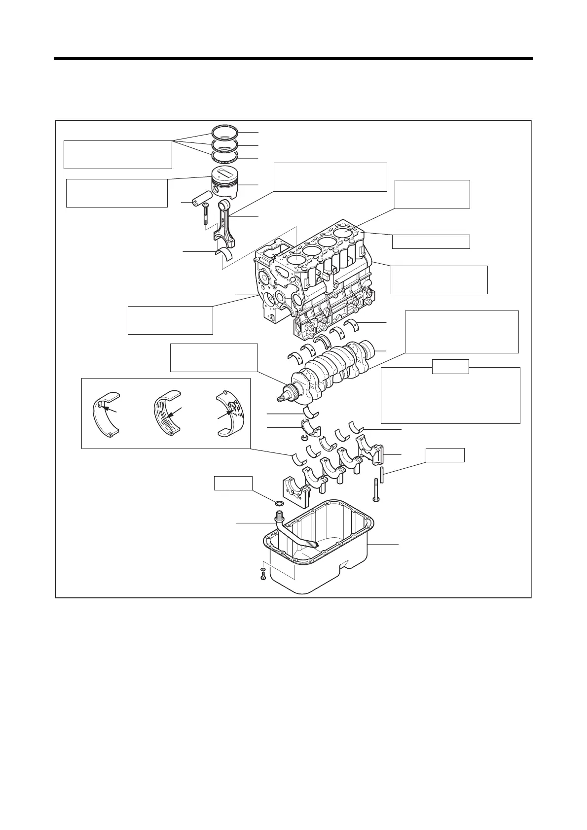
4. Disassembling and inspecting cylinder block, crankshaft, piston and oil pan
Disassembling and inspecting cylinder block, crankshaft, piston and oil pan
Disassembling sequence
Note: When replacing the cylinder block, carefully remove parts (relief valve, etc.) mounted on the non-reusable cylinder block
so that they can be reused.
1 Oil pan 7 No.1 compression 12 Main bearing cap
2 Oil screen 8 No.2 compression 13 Lower main bearing
3 Connecting rod cap 9 Oil ring 14 Crankshaft
4 Lower connecting rod
bearing
10 Piston
(Remove parts 5 to 10 as a unit)
15 Upper main bearing
16 Cylinder block
5 Connecting rod 11 Upper connecting rod
bearing
6 Piston pin
Seizing
Scoring
Pealing
7
8
9
10
5
6
11
16
15
14
13
12
4
1
3
2
Piston ring wear, damage,
Ring gap clearance
Piston wear, seizure,
streak, ring groove wear
Cylinder damage,
stepped wear
Connecting rod bend, twist,
Big end thrust clearance
Crank journal/pin damage,
uneven wear, cracks, bend,
Clogged oil hole
Top face distortion
Damaged plugs and
knock pins
Dirty or clogged oil and
water galleries
Damaged crankshaft
gear teeth
Replace
The main bearings may be seized
due to poor oil maintenance etc.
In that case, the crankshaft must
be replaced.
Caution
Replace
 Loading...