1
2
3
A
6
7
8
Appendix 3 Device Point Assignment Sheet
APPENDICES
APPX - 12
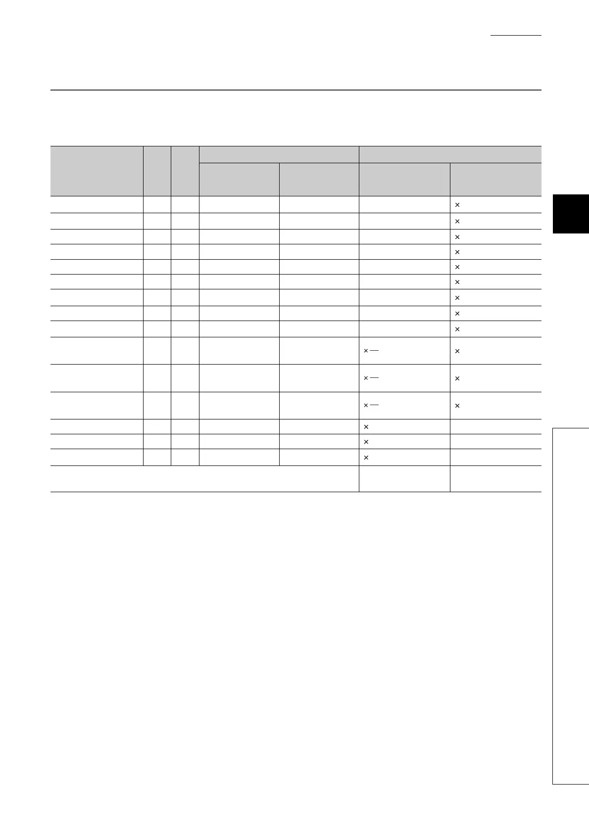
Appendix 3 Device Point Assignment Sheet
(1) For the Basic model QCPU
*1: The points are fixed for the system. (Cannot be changed)
*2: Up to 32K points can be set for each device.
*3: Enter the values multiplied (or divided) by the number shown in the Size (words) column.
TableAPPX.9 Device point assignment sheet
Device name
Sym-
bol
Num
eric
nota-
tion
Number of device points
*2
Restriction check
Points Range
Size (words)
*3
Points (bits)
*2
Input relay
*1
X 16 2K (2048) X0000 to 07FF /16 128
1
2048
Output relay
*1
Y 16 2K (2048) Y0000 to 07FF /16 128
1
2048
Internal relay M 10 K ( ) M0 to /16
1
Latch relay L 10 K ( ) L0 to /16
1
Link relay B 16 K ( ) B0000 to /16
1
Annunciator F 10 K ( ) F0 to /16
1
Link special relay
*1
SB 16 1K (1024) SB0000 to 03FF /16 64
1
1024
Edge relay V 10 K ( ) V0 to /16
1
Step relay
*1
S 10 2K (2048) S0 to 2047 /16 128
1
2048
Timer T 10 K ( ) T0 to
2
Retentive timer ST 10 K ( ) ST0 to
2
Counter C 10 K ( ) C0 to
2
Data register D 10 K ( ) D0 to
1
-
Link register W 16 K ( ) W0000 to
1
-
Link special register
*1
SW 16 1K (1024) SW0000 to 03FF
1
1024 -
Tota l
(16704 or less)
 Loading...