5-3
5
5.1.3 Cable connection diagram
Use an RS-485 cable to make the connection. Make sure cables are no longer than 500m if you make your own
cable. Connect the connector on the inverter side of the cable into the PU port. Connect the GOT side of the
cable into the D-Sub (subminiature) 9-pin.
8.
1.
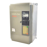
When seen from the front of the
inverter (receptacle side)
Pin layout in the PU port
D-Sub (subminiature) 9-pin
Modular jack
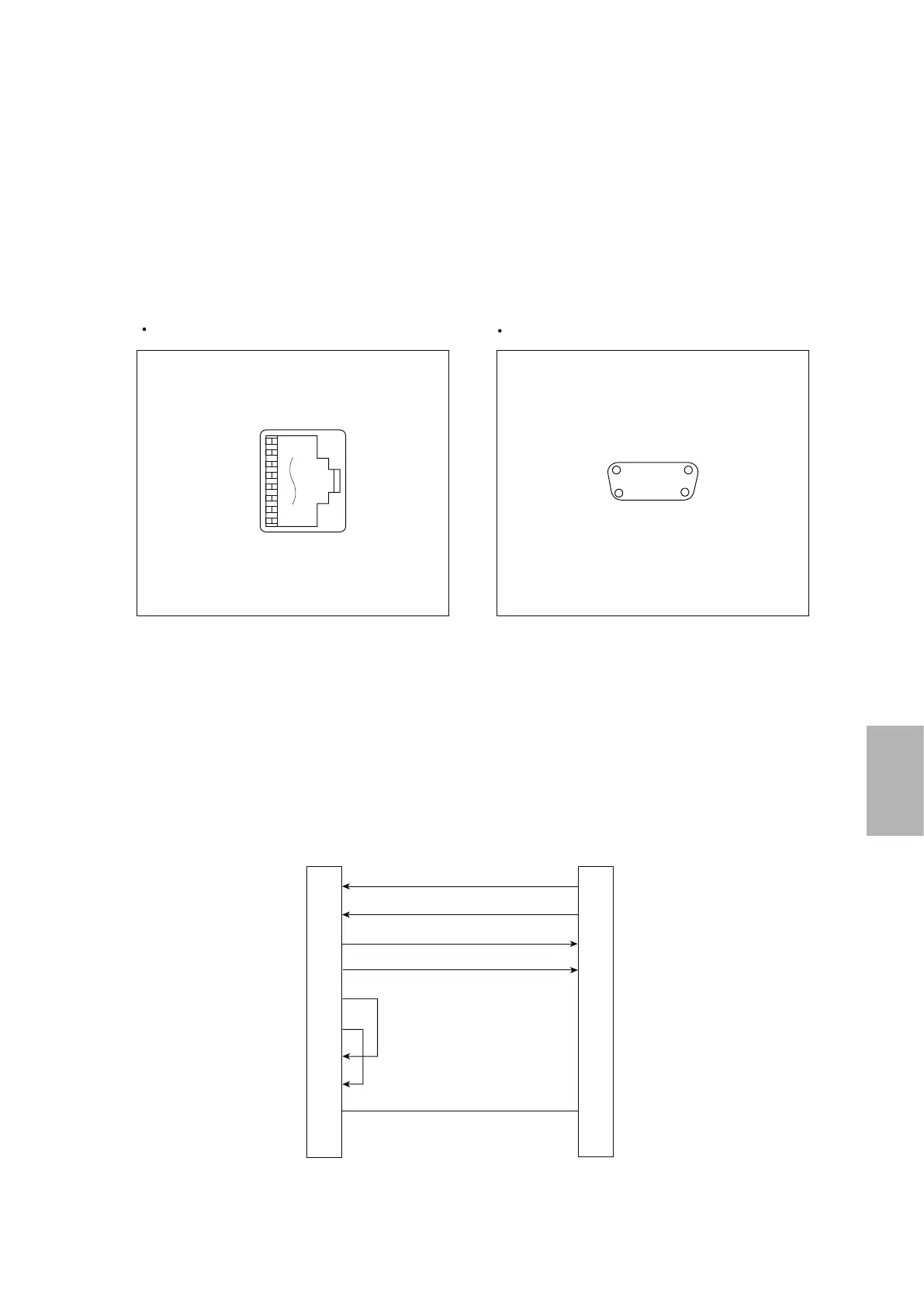
D-Sub (subminiature) 9-pin (female)
GOT main part connector
see from the front
51
96
The following diagram shows the connection between the GOT and the inverter.
Wiring diagram
● RS-485 connection diagram
GOT side*
1
*1 Set the terminating resistor to "Disable".
RDA
SDA
SDB
RSA
RSB
CSA
CSB
SG
FG
5
4
3
6
2
8
ー
ー
1
2
7
1
6
3
8
4
9
5
ー
SDA
SDB
RDA
RDB
P5S
P5S
ー
ー
SG
Inverter or distributor side
(modular connector)

 Loading...