294
ROTC
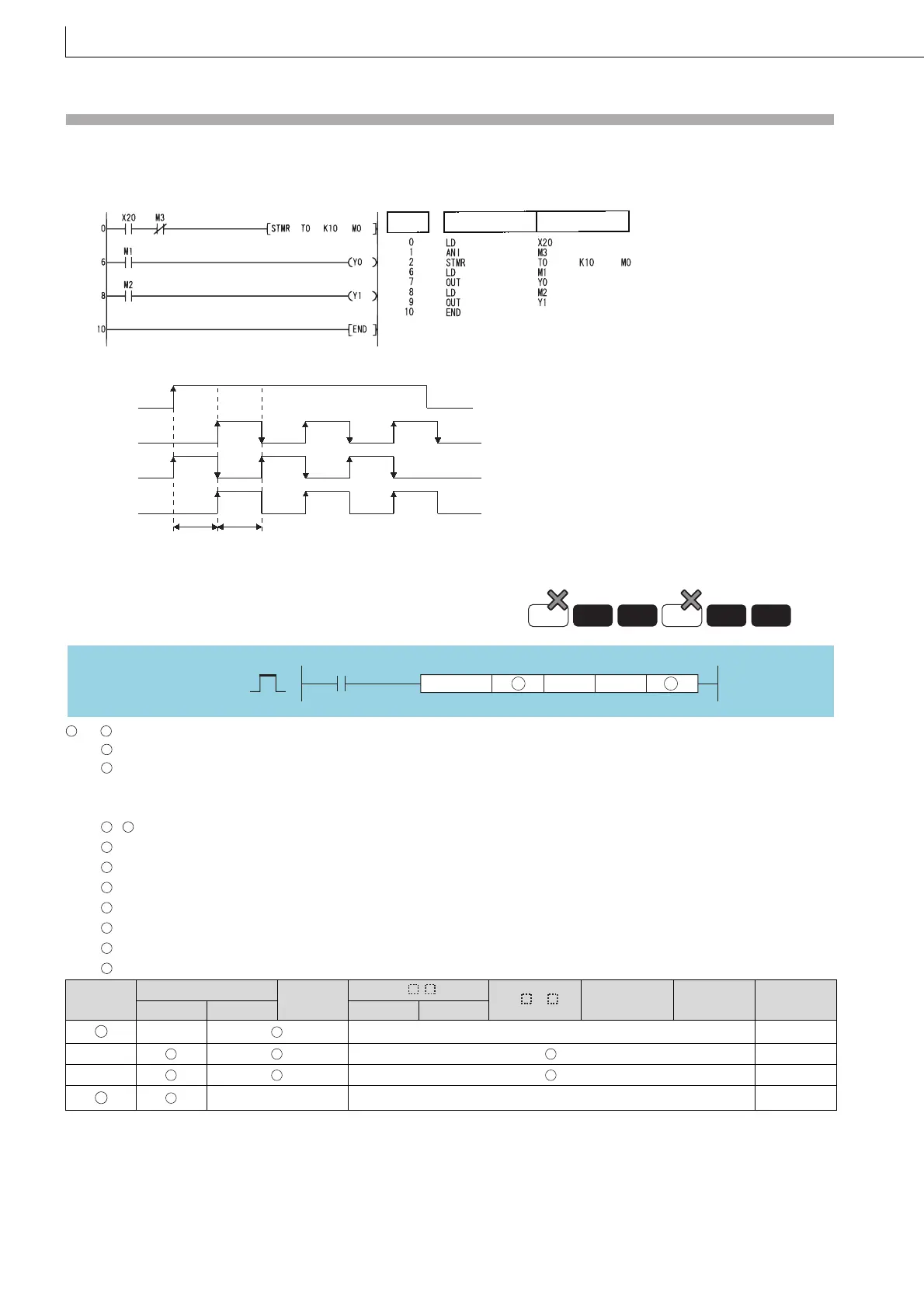
Program Example
(1) The following program turns Y0 and Y1 ON and OFF once each second (flicker) when X20 is ON.
(Uses 100 ms timer)
[Ladder Mode] [List Mode]
[Timing Chart]
: + 0: Measures the number of table rotations (for system use) (BIN 16 bits)
+ 1: Call station number (BIN 16 bits)
+ 2: Call item number (BIN 16 bits)
n1 : Number of divisions of table (2 to 32767) (BIN 16 bits)
n2 : Number of low-speed sections (value from 0 to less than n1) (BIN 16 bits)
: + 0: A phase input signal (bits)
+ 1: B phase input signal (bits)
+ 2: 0 point detection input signal (bits)
+ 3: High speed forward rotation output signal (for system use) (bits)
+ 4: Low speed forward rotation output signal (for system use) (bits)
+ 5: Stop output signal (for system use) (bits)
+ 6: Low speed reverse rotation output signal (for system use) (bits)
+ 7: High speed reverse rotation output signal (for system use) (bits)
6.8.5 ROTC Rotary table shortest direction control
6.8.5
ROTC
Setting
Data
Internal Devices
R, ZR
J\
U\G
Zn
Constants
K, H
Other
Bit Word Bit Word
–– –– ––
n1 ––
n2 ––
–– –– ––
Step
Instruction
Device
M1, Y0
X20
M2, Y1
M3
1 sec 1 sec
Basic
Redundant
Process
High
performance
Universal
LCPU
Command
ROTC
n2n1
S D
ROTC
S S
S
S
D D
D
D
D
D
D
D
D
S
D

 Loading...

