31
2
3
4
5
6
7
8
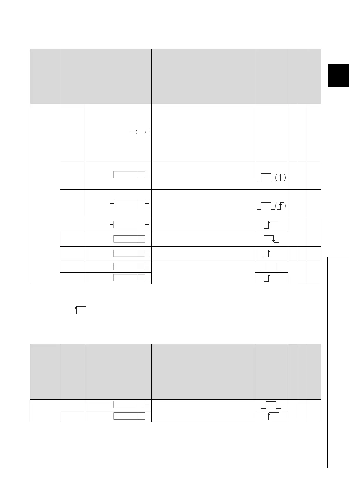
2.3 Sequence Instructions
2.3.3 Output instructions
2.3.3 Output instructions
*1: The number of steps may vary depending on the device being used.
See description pages of individual instructions for number of steps.
*2: The execution condition applies only when an annunciator (F) is in use.
2.3.4 Shift instructions
Category
Instruction Symbol
Symbol Processing Details
Execution
Condition
Number of Basic Steps
Subset
See for Description
Output
OUT • Device output
*1
-
Page
139
Page
141
Page
144
Page
146
SET • Sets device
*1
-
Page
147
Page
150
RST • Resets device
*1
-
Page
148
Page
150
PLS
• Generates 1 cycle program pulse at leading
edge of input signal.
2-
Page
152
PLF
• Generates 1 cycle program pulse at trailing
edge of input signal.
FF • Reversal of device output 2 -
Page
154
DELTA
• Pulse conversion of direct output 2 -
Page
155
DELTAP
Category
Instruction Symbol
Symbol Processing Details
Execution
Condition
Number of Basic Steps
Subset
See for Description
Shift
SFT
• 1-bit shift of device 2 -
Page
157
SFTP
SET D
*2
RST D
*2
PLS D
PLF D
FF
D
DELTA D
DELTAP D
SFT D
SFTP D

 Loading...

