62
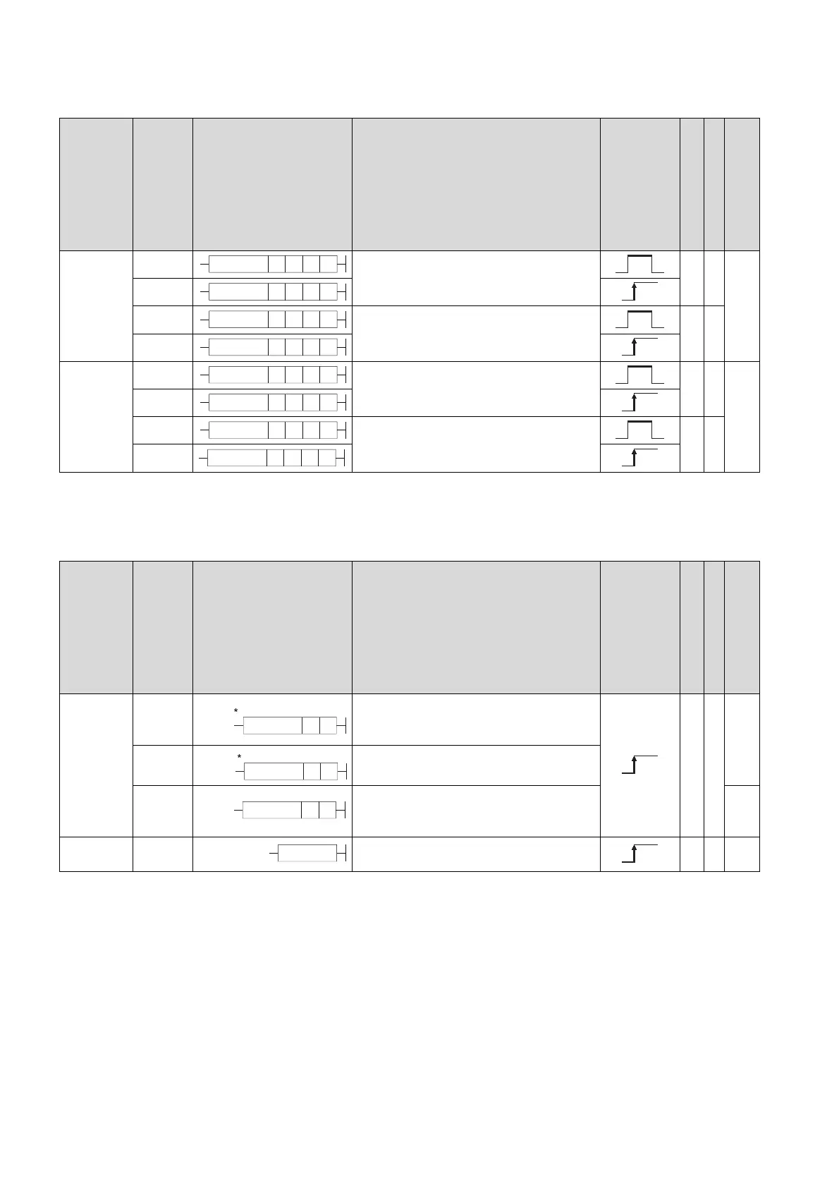
2.5.8 Buffer memory access instructions
2.5.9 Display instructions
Category
Instruction Symbol
Symbol Processing Details
Execution
Condition
Number of Basic Steps
Subset
See for Description
Data read
FROM
• Reads data in 16-bit units from an intelligent
function module.
5-
Page
426
FROMP
DFRO
• Reads data in 32-bit units from an intelligent
function module.
5-
DFROP
Data write
TO
• Writes data in 16-bit units to an intelligent
function module.
5-
Page
428
TOP
DTO
• Writes data in 32-bit units to an intelligent
function module.
5-
DTOP
Category
Instruction Symbol
Symbol Processing Details
Execution
Condition
Number of Basic Steps
Subset
See for Description
ASCII print
PR
• Outputs ASCII code of 8 points (16
characters) from device designated by (S) to
output module.
3-
Page
432
PR
• Outputs ASCII code from device designated
by (S) to 00
H
to output module.
PRC
• Converts comments from device designated
by (S) to ASCII code and outputs to output
module.
Page
434
Reset LEDR
• Resets annunciator and LED indicator
display.
1-
Page
437
FROM n3n1 n2 D
FROMP n3n1 n2 D
DFRO n3n1 n2 D
DFROP n3n1 n2 D
TO n3n1 n2 S
TOP n3n1 n2 S
DTO n3n1 n2 S
DTOP n3n1 n2 S
When SM701 is OFF
PR S D
When SM701 is ON
PR S D
PRC SD
LEDR

 Loading...

