29
2
3
4
5
6
7
8
2.3 Sequence Instructions
2.3.1 Contact instructions
2.3 Sequence Instructions
2.3.1 Contact instructions
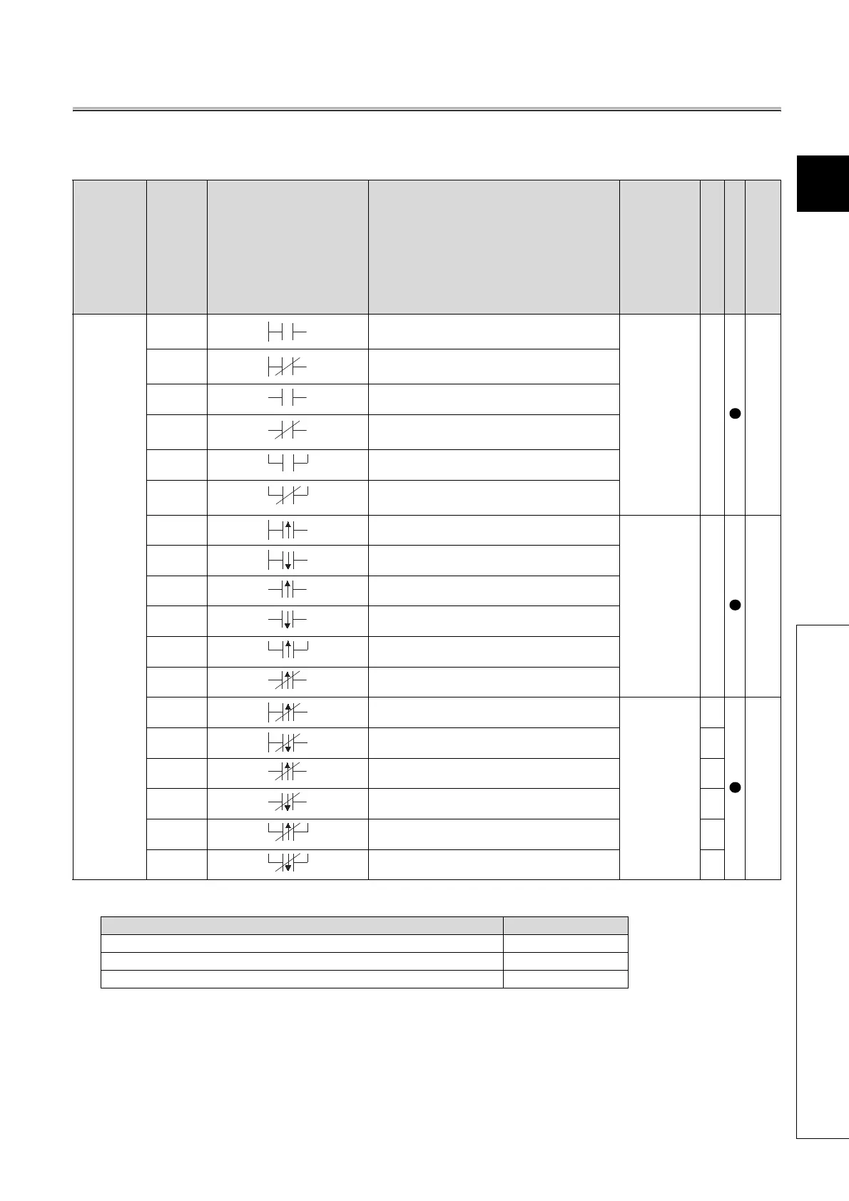
*1: The number of steps may vary depending on the device being used.
Category
Instruction Symbol
Symbol Processing Details
Execution
Condition
Number of Basic Steps
Subset
See for Description
Contact
LD
• Starts logic operation
(Starts a contact logic operation)
*1
Page
124
LDI
• Starts logical NOT operation
(Starts b contact logic operation)
AND • Logical product (a contact series connection)
ANI
• Logical product NOT (b contact series
connection)
OR • Logical sum (a contact parallel connection)
ORI
• Logical sum NOT (b contact parallel
connection)
LDP • Starts leading edge pulse operation
*1
Page
126
LDF • Starts trailing edge pulse operation
ANDP • Leading edge pulse series connection
ANDF • Trailing edge pulse series connection
ORP • Leading edge pulse parallel connection
ORF • Trailing edge pulse parallel connection
LDPI • Starts leading edge pulse NOT operation
3
*2
Page
128
LDFI • Starts trailing edge pulse NOT operation
3
*2
ANDPI • Leading edge pulse NOT series connection
4
*2
ANDFI • Trailing edge pulse NOT series connection
4
*2
ORPI • Leading edge pulse NOT parallel connection
4
*2
ORFI • Trailing edge pulse NOT parallel connection
4
*2
Device Number of Steps
Internal device, file register (R0 to R32767) 1
Direct access input (DX) 2
Devices other than above 3

 Loading...

