416
IXDEV, IXSET
: Head number of the devices where index modification data is stored (pointer only) P (Pointer)
: Head number of the devices where index modification data will be stored (except a pointer) (BIN 16 bits)
Function
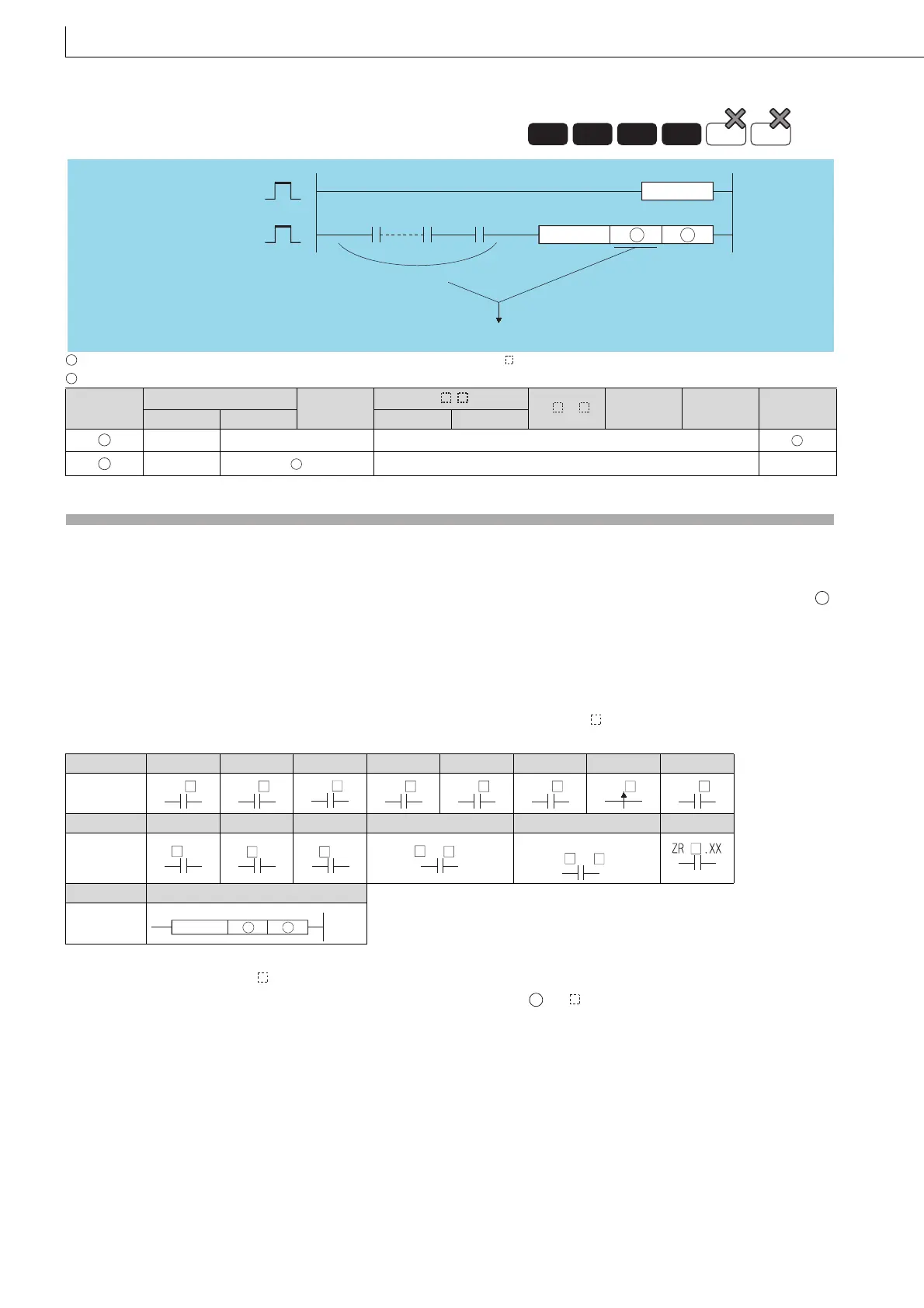
(1) The IXDEV and IXSET instructions are used to configure an index modification table used in the IX and IXEND
instructions.
(2) The device offset value designated at the offset designation area is set at the index modification table designated by .
(3) The value 0 will be entered if no designation is made.
(4) Word devices are also indicated by contact (word device bit designation). Data register 10 (D10) is designated with
D10.0.
(Any value from 0 to F can be used for the bit number.)
(5) Designation is made according to the method described below. *
1
(The symbol is where the offset value will be. The
notation XX indicates random selection.)
*1: When using a basic model QCPU, the devices R, U/G, J, ZR and P cannot be used.
*2: Devices following J \ designate B, W, X, or Y, and the offset value is also set in correspondence with this.
*3: When using a basic model QCPU, specify a dummy device number. is P .
(6) If two offsets for two identical types of device have been set in the offset designation area, the last value set will be valid.
(7) The IXDEV and IXSET instructions should be treated as a pair.
(8) Any value from 0 to 32767 is valid for ZR. (The offset value will be the remainder of the quotient of the designated device
number divided by 32768.)
7.6.13 IX DEV, IXSET Designation of modification values in index modification
of entire ladder s
7.6.13
IXDEV, IXSET
Setting
Data
Internal Devices
R, ZR
J\
U\G
Zn Constants
Other
P
Bit Word Bit Word
–– –– ––
–– –– ––
Device T C X Y M L V B
Designation
method
Device D W R U/G J ZR
Designation
method
Device P
Designation
method
Universal
LCPU
Basic
Process
High
performance
Redundant
IXDEV
IXSET
IXDEV
IXSET
Dummy contact
Offset designation sections
D
S
S
D
S
D
D
T C
X
Y M
L
V
B
D
.XX
W
.XX
R
.XX
\
G
.XX
U
\
B
J
*2
IXSET
DS
*3
S

 Loading...

