3-16 Theory of Operation: Main Board
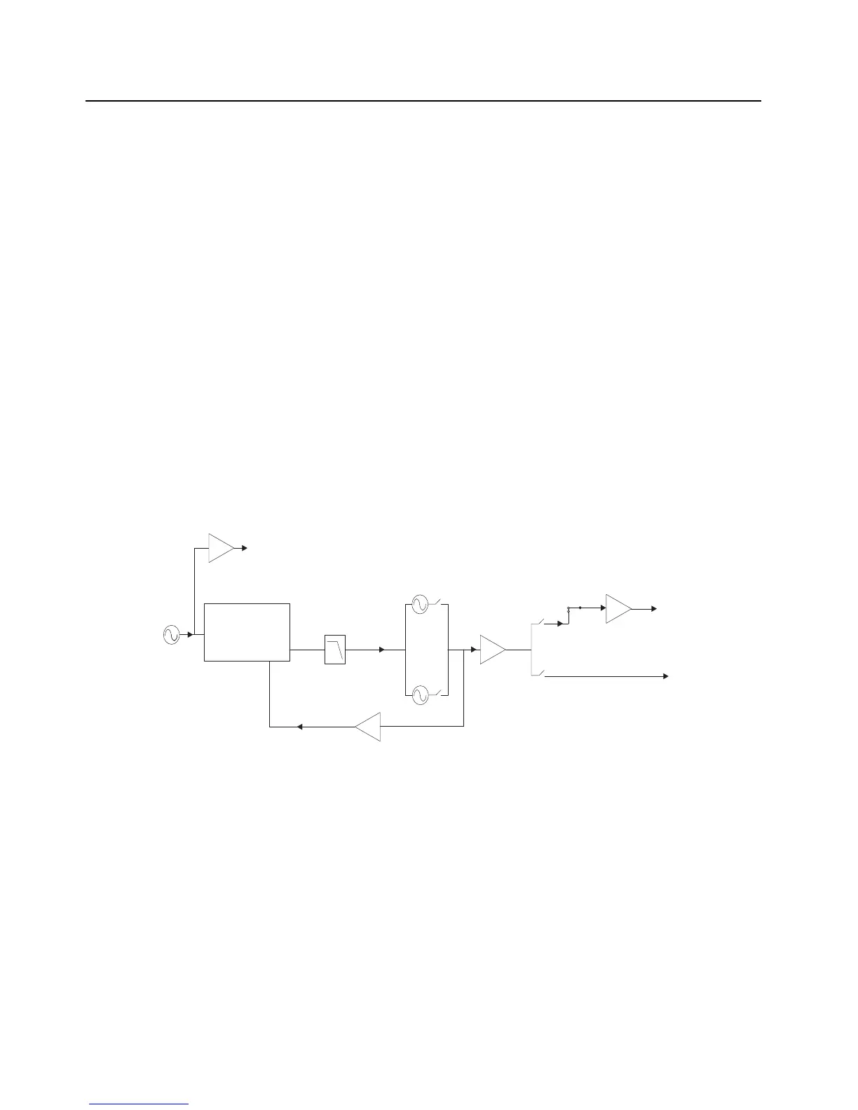
3.1.4 Frequency Generation Unit (FGU)
The frequency-generation function is performed by several ICs; multiple voltage-controlled
oscillators (VCOs); and associated circuitry. The reference oscillator provides a frequency standard
to the Trident IC, which controls the VCOs via the port expander. There are also buffers that amplify
the VCO signal to the correct level for the next stage. Figure 3-13, Figure 3-14, Figure 3-15 and
Figure 3-16 below shows a block diagram of the FGU Section.
VHF: Two VCOs are employed: one to generate the first RX LO and the other to generate the
transmit injection signals.
UHF1/UHF2: Two VCOs are employed: one to generate the first RX LO and the other to generate
the transmit injection signals.
700/800 MHz: Three VCOs are used to cover the entire 700/800 MHz band.
• VCO1 covers the RX 800 MHz band and the TX 700 MHz (764–776 MHz) band
• VCO2 covers the TX 700/800 MHz (794–824 MHz) band
• VCO3 covers the TX 800 MHz (851–870 MHz) band and the RX 700 MHz band
900 MHz: Two VCOs are employed: one to generate the first RX LO and the other to generate the
transmit injection signals.
NOTE: Refer to Table 8-1, “List of Transceiver Schematics and Board Overlays,” on page 8-1 for a
listing of FGU-related schematics that will aid in the following discussion.
Figure 3-13. Synthesizer Block Diagram (VHF)
TRIDENT IC
LOOP
FILTER
PRESCALAR
BUFFER
16.8MHz
16.8MHz
BUFFER
PRE
BUFFER
TX LO
RX LO
TX
BUFFER
VHF TX
VHF RX
16.8 MHz REFERENCE CLOCK (To Controller and Abacus IC)
TX VCO
RX VCO
 Loading...