3-54 Theory of Operation: Global Positioning Sytem (GPS)
.
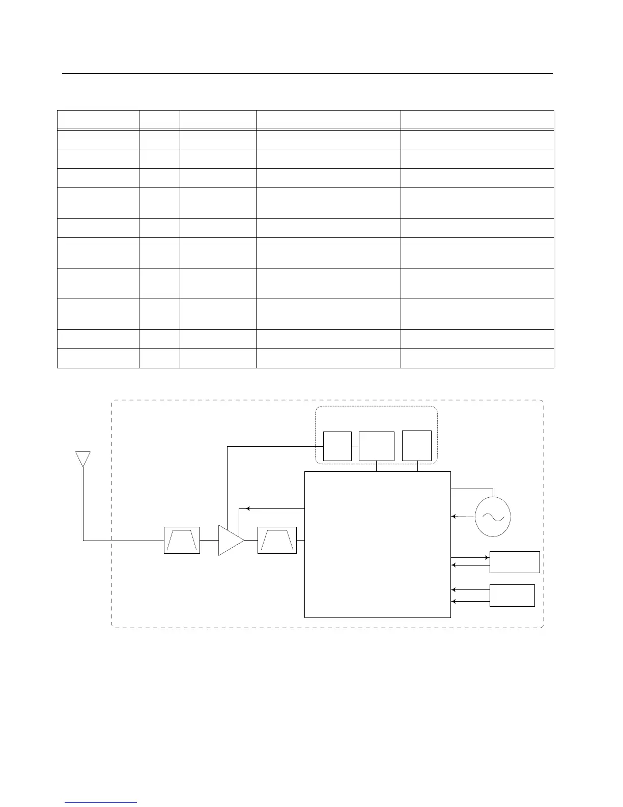
Figure 3-40. GPS Block Diagram
Table 3-11. Power and I/O Pins for NL5500
Signal Name Type NL5500 ball(s) Source/Destination [ref] (board Description
VBAT Power A2, H1, D8 VSW_3.6 [U6504] (
Main Board) Main NL5500 power supply
VDDS Power B3, G10, K5, E2 VCC_1.85 [U6508] (
Main Board) I/O Power Supply
VDD_TCXO Power G1 VSW_3.6 [U6504] (
Main Board) TCXO Power Supply
RTC_CLK Clock H9 CPLD IO74 [U6101] (
Main
Board)
32kHz RTC
TCXO_CLK_LV Clock F1 TCXO [Y1304] (
Main Board) 26MHz TCXO
GPS_nShutdown Input D5 CPLD IO91 [U6101] (
Main
Board)
GPS Reset
GPS_UART_TX Output F5 OMAP pin R9 [U6302] (
Main
Board)
GPS UART TX to OMAP UART RX
GPS_UART_RX Input E3 OMAP pin M18 [U6302] (
Main
Board)
OMAP UART TX to GPS UART RX
LNA_ENABLE Output H6 LNA [U1304] (
Main Board) GPS External LNA Enable
GPS_LNA_IN Input L2 GPS antenna/front-end GPS RF Input from antenna
GPS IC
TI NL5500
GPS_LNA_IN (L2)
GPS_EXT_LNA_EN (H6)
TCXO_CLK_LV (F1)
TCXO
26MHz,
<0.5ppm
GPS_UART_TX (F5)
GPS_UART_RX (E3)
UART2 Rx (R9)
UART2 Tx (M18)
[OMAP 1710]
GPS Tx
GPS Rx
GPS_NSHUTDOWN (D5)
RTC_CLK (H9)
32kHz RTC
[CPLD]
IO74 (E2)
IO91 (D12)
Reset
External Regulators
1.8V
(VCC_1.85)
2.8V
LNA Enable
LNA
Ant
Main Board
3.6V
(VSW_3.6)
SAW SAW
VDD_TCXO (G1)
VBAT VDDS
 Loading...