3-46 Theory of Operation: Controller
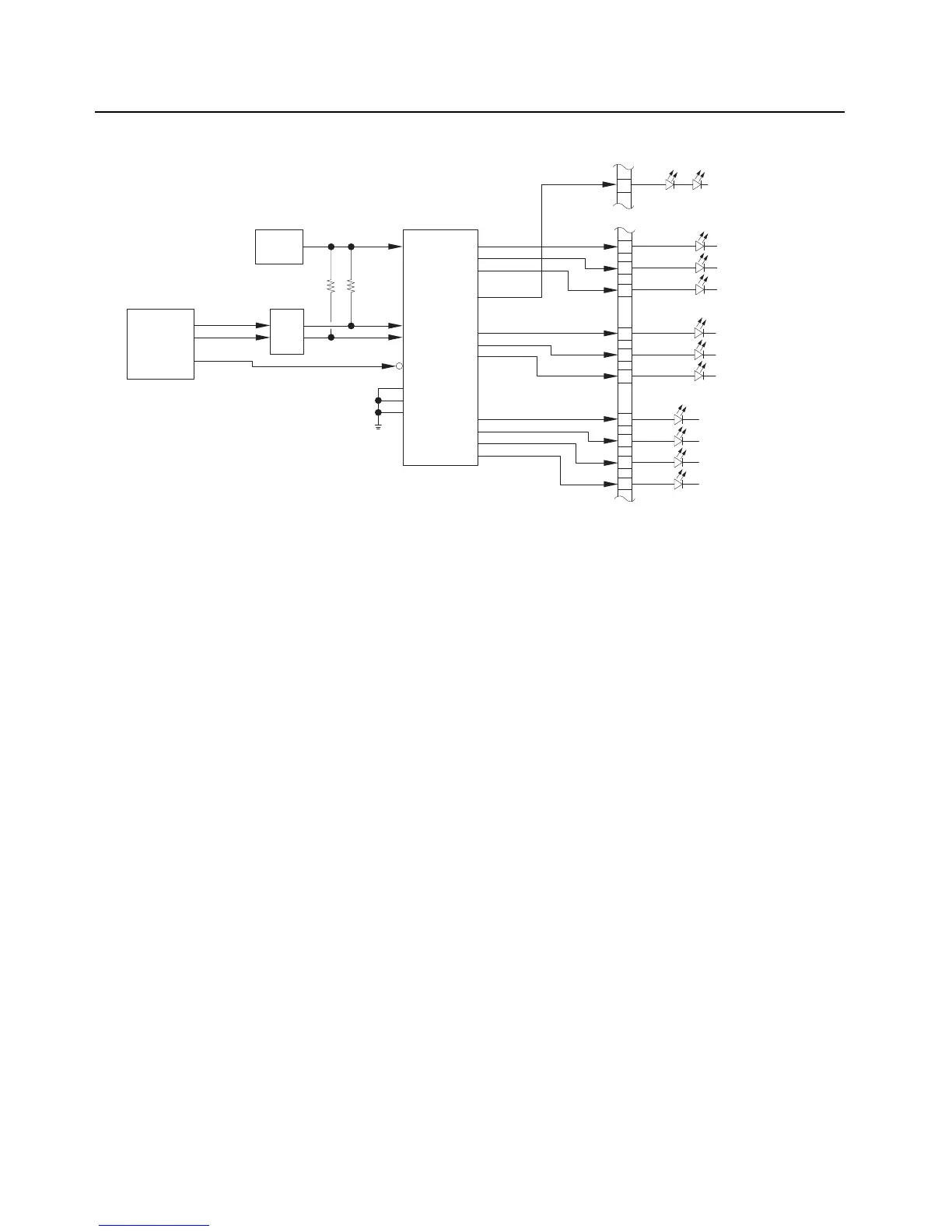
Figure 3-35. Lighting Controller Overview
3.2.6.4 Keypad
The Full Keypad Model contains a 21 button keypad, which translates to a 5x5 row and column
keypad matrix as shown in Figure 3-36. The keypad also contains LEDs for the backlighting of the
keys, which is described in more detail in Section 3.2.6.3: "Intelligent Lighting". Every key is assigned
a particular row and column to identify the unique key, as shown in keypad mapping Table 3-7. The
keypad board also contains 2, 6-channel filters that each row and column signal passes through.
Each row of the keypad contains an external pull-up resistor, and all the rows are interrupt based
inputs to OMAP. The columns are driven low by default in OMAP. When a key is pressed, the
corresponding key row and column are shorted together and causes a low level to be input on the
corresponding row in OMAP. Upon receiving the row interrupt, the OMAP IC is then programmed to
scan the column output to determine which corresponding column was selected that generated the
interrupt.
OMAP
VOUT
V_SW_5
V-REG
LED DRIVER
J2301
J2302
KEYPAD WHITE
ILLUMINATION
STATUS
R
53
55
57
58
60
56
32
34
36
38
G
A
R
G
A
TX/RX
FRONT DISPLAY
WHITE BACKLIGHT
PWR
LED0
LED1
LED2
LED3
LED4
LED5
LED6
LED8
LED9
LED10
LED11
SCL
SDA
RESET
A0
A1
A2
(LP3943)
LEVEL
SHIFT
(12C) SCL
(12C) SDA
RST_OUT

 Loading...