Theory of Operation: Bluetooth 3-65
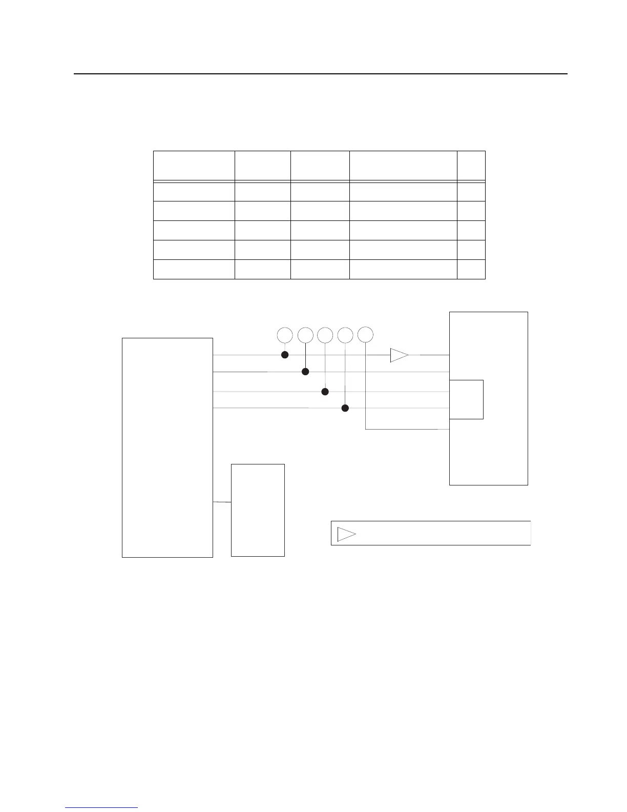
The host processor is connected to the 3.3V SDRAM using a synchronous interface. The host
processor is connected to the OMAP on the Main Board by a full-speed USB (D11 & D12). VBus is a
sense line only.
Figure 3-52. Bluetooth USB Interface To Main Board
The ATMEL bootloader is being used as a first stage bootloader that will jump to the Motorola
bootloader, which is a stage two bootloader. GPIO20 is used by the ATMEL bootloader to trap in
Flash mode. GPIO19 will be used by the Motorola bootloader to trap in Flash mode. Both pins are
active low.
Table 3-16. USB I/O
Signal Name Pin Name Pad Name Keypad Board
Schematic Name
I/O
GPIO19 C12 PA19 USB_BOOT_3.3V I
GPIO20 D10 PA20 ATMEL_BOOT I
DP D11 – BT_AVR_USB_DP I/O
DM D12 – BT_AVR_USB_DM I/O
VBUS E12 – BT_AVR_VBUS I
USB_BOOT
ATMEL_BOOT
APX2000 Keypad Board 60-pin Connector
BT Debug Flex
ATMEL AVR32
AT32UC3A0512
PA19
VBUS
DP
DM
USB
PA20
C12
E12
D11
D12
D10
Pin 21
Pin 3
Pin 41
Pin 43
Factory Test Points
= Level Translator. 3.3 volts on AVR side
//
 Loading...