Chapter 7 Troubleshooting Tables
7.1 List of Board and IC Signals
Due to the nature of the schematic-generating program, signal names might be different when they
are not directly connected to the same point. The tables in this chapter provide a cross reference to
the various pinouts for these signals. Table 7-1 lists and provides links to each of the tables in this
chapter.
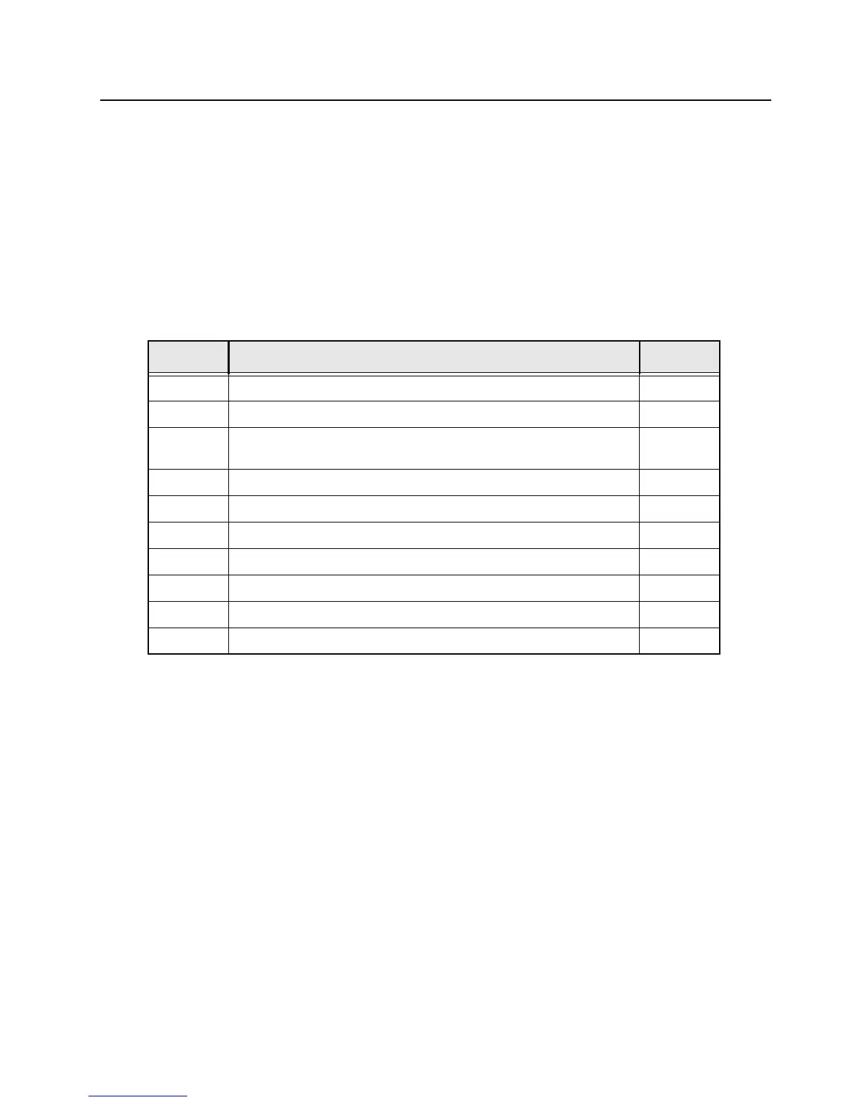
Table 7-1. List of Tables of Board and IC Signals
Table No. Table Name Page No.
7-2
Mainboard to Keypad flex connector interface Pin-Out 7-2
7-3
Main Keypad flex connector to main board connector Interface Pin-Out 7-5
7-4
Main Keypad flex connector to keypad board connector Interface Pin-
Out
7-8
7-5
Keypad board connector to mainboard Interface Pin-Out 7-11
7-6
Keypad board connector to front kit flex Interface Pin-Out 7-14
7-7
Front kit connector Interface Pin-Out 7-16
7-8
GCAI flex connector Interface Pin-Out 7-21
7-9
PTT flex connector Interface Pin-Out 7-23
7-10
Overall GPIO pin functions 7-24
7-11
Primary IC Reference Designator 7-32
 Loading...