Theory of Operation: Controller 3-23
3.2 Controller
3.2.1 Controller Overview
This section provides a detailed circuit description of the APX 2000/ APX 4000/ APX 4000Li/
APX 1000 (900 MHz) controller design. The controller design consists of the following board and
flexes:
Printed Circuit Boards
• Main Board
• Keypad Board
Flexes
• GCAI (Global Core Accessory Interface) (BT Antenna/TX/RX LED)
• Side Controls
• Backkit (keypad and mainboard)
• Frontkit (audio/speaker/knob/front display)
•Mic
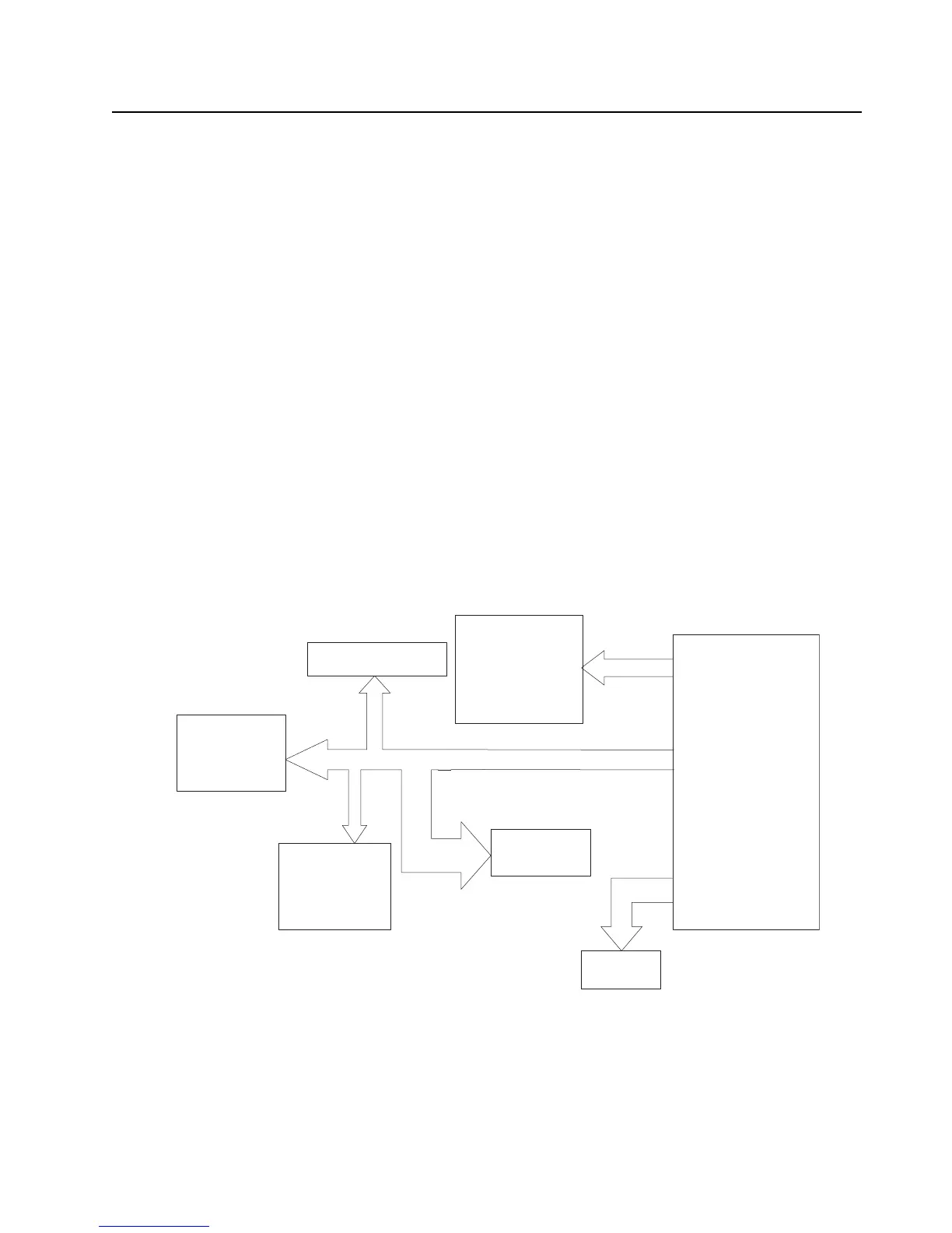
The controller interconnection diagram (Figure 3-17.) shows the various physical components of the
design, along with how they are all connected. It also shows the key distinguishes between a flex
connection and a board-to-board connection. A brief description of each of the components is
provided below.
Figure 3-17. Controller Interconnection Diagram
Keypad
Board
GCAI
Front display
Speaker
and knob
Side
control
Main board
Mic
 Loading...