Theory of Operation: Controller 3-25
3.2.1.2.5 E-Button Flex
The E-button flex contains a toggle switch for Emergency Calling and connector to GCAI flex.
3.2.1.3 Controller Electrical Architecture
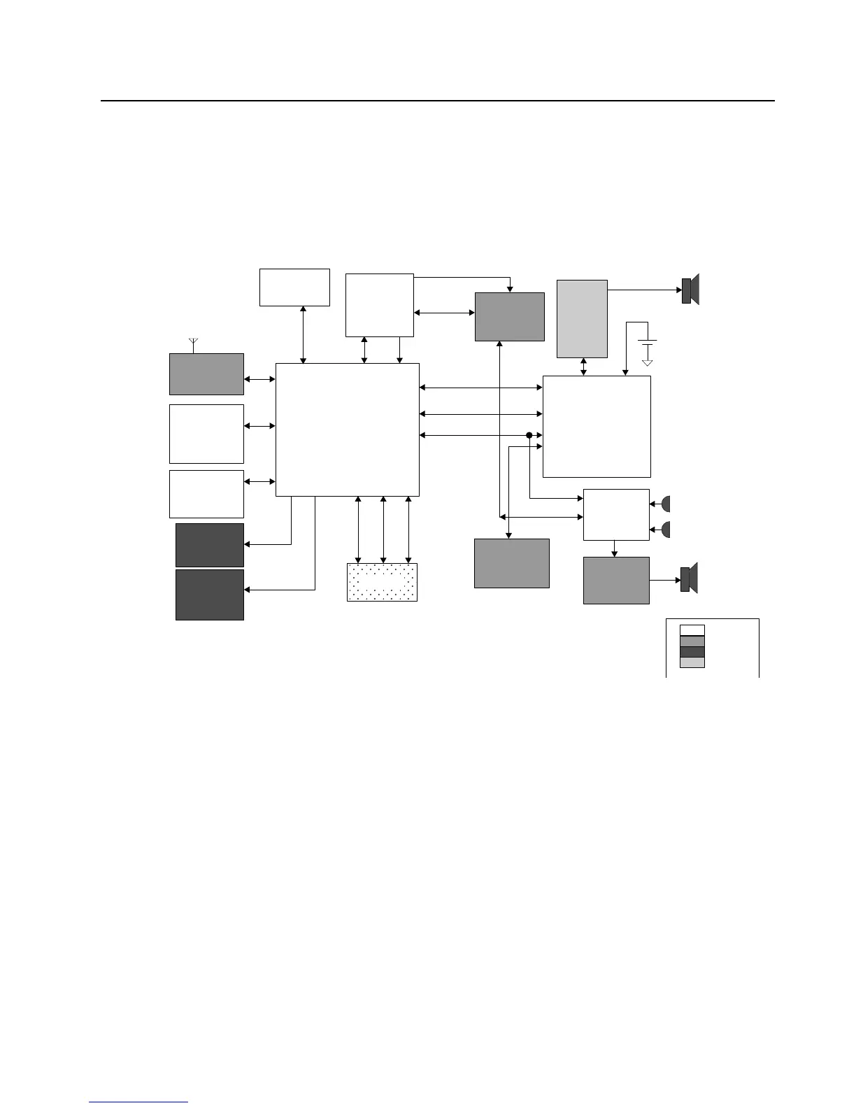
An overview of the Controller electrical architecture is shown in Figure 3-18 below. The major
components and electrical interfaces are shown.
Figure 3-18. Controller Electrical Overview
The functional blocks of the controller are:
• DC Distribution
• Clock Sources
• Processor / Memory
•CPLD
• Audio – Internal and External
• MAKO
• User Interfaces
GPS/ BT Chipset
(TINL5500)
FLASH
64MB
SDRAM
32MB
Keypad /
Switches
Front
Display
SoSSI
Keypad
EMIFF
EMIFS
UART 2
12C
Lighting
Controller
CPLD
EMIFS
32 kHz Clk
SSI MACE
Secure
IC
Side
Conn -
GCAI
Radio
Battery
Accessory
Audio
MAKO IC
SPI
Codec
Dual
Microphones
Main
Speaker
Main Board
Keypad
UI
GCAI
Class D
Audio PA
GPS/BT Module
(TINL5500 &
ATMEL AVR32)
RF Section
GPIOSPISSI
SPI
USB / UART
Audio SSI 1
OMAP 1710
Processor
+
-
4.096 MHz Clk
 Loading...