3-30 Theory of Operation: Controller
3.2.2.1.3 External Switcher 5
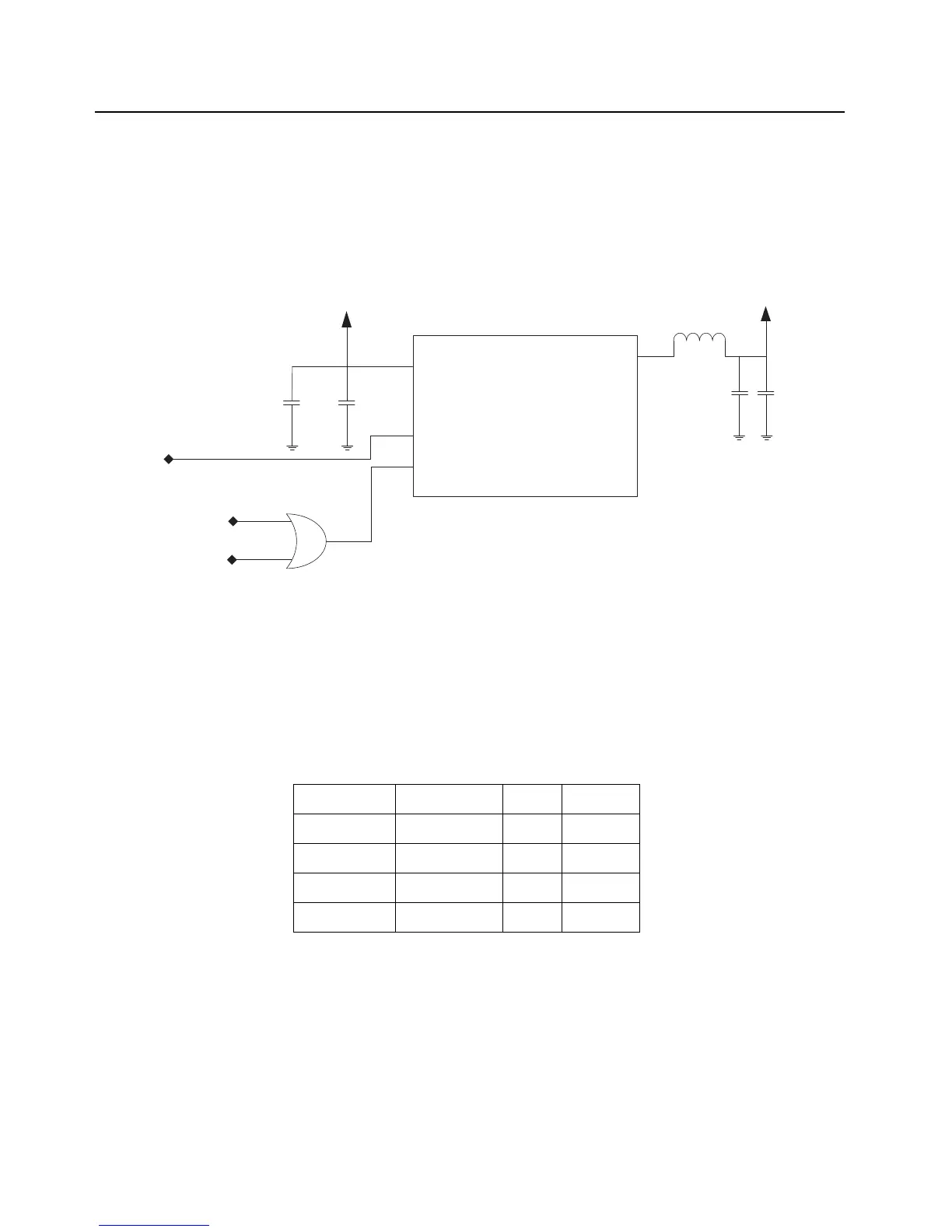
The controller board uses an external TI regulator (TPS62110, U6505) to regulate to 5.4V. The
TPS62110 is a 1.5A capable synchronous step down converter. The output is adjusted using a
voltage divider to the feedback pin. The regulator is powered from SW_B+. Figure 3-21.illustrates
the SW5 circuitry. The SW5 circuit also includes or-gate logic that facilitates implementation of
current saving PFM mode when the radio is in standby mode.
Figure 3-21. 5V Switched Power Supply
APX 2000/ APX 4000/ APX 4000Li/ APX 1000 (900 MHz) has Pulse Switching option.
Mode 1: Pulse Frequency Modulation (PFM). A relatively noisy but highly efficient pulsing mode for
Switched power supplies.
Mode 2: Pulse Width Modulation (PWM). Pulsing mode that is cleaner than PFM, used when risk of
RF interference is present which includes both transmit and receive radio modes.
Table 3-4. Pulse Switching Combination
PA_SHTDN 5V_PWM_EN SYN MODE
000PFM
011PWM
101PWM
111PWM
L6504
C6566
C6567
V_SW_5
VIN
U6505
TPS62110
VOUT
EN
SYNC
C6565
SW_B+
BGAP_COMP
PA_SHTDN
5V_PWM_EN
C6549
 Loading...