Theory of Operation: Controller 3-43
3.2.6.1.2 APX 2000/ APX 4000 (Two Knobs)
The Top Control contains an On/Off & Volume Knob, a sixteen-position Channel/Frequency Switch,
and an emergency button. The Top Control also includes a TX/RX LED that is solid amber upon
receive, red on PTT, and blinks amber on secure RX and a status LED. The Top Control components
are mounted on flex.
When the On/Off & Volume Knob(S3) is switched to the 'ON' position, the switch is grounded and
MECH_SW is pulled low. MECH_SW is an input to MAKO (U6501). The logic low input enables an
external FET (Q6501) gate voltage, FET_ENX, which switches UN_SW_B+ to SW_B+ and turns the
radio on. Volume is also controlled through S3 and is an input to MAKO. The VOL signal is
connected to a potentiometer biased between ground and 2.775 V (R246) from MAKO. When the
volume knob is turned, the VOL signal level is converted to a code word by MAKO's ADC and read
by OMAP through SPI.
The orange programmable Top Button (S1) is typically used for emergency. It is also biased to
1.875 V (R6507) and is an input (EMERG_BTN_X) to the CPLD. A button press is detected when
EMERG_BTN_X is pulled low.
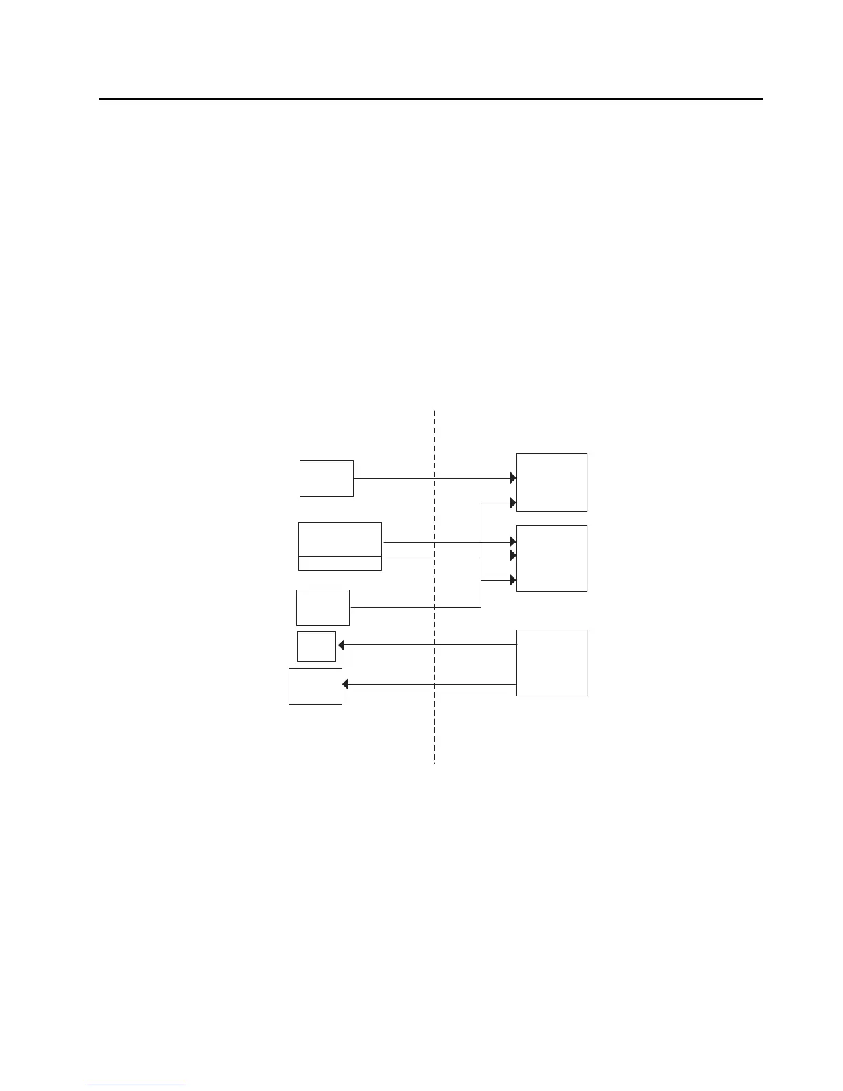
Figure 3-33. Control Top Block Diagram (APX 2000/ APX 4000 (Two Knobs))
CPLD
Volume POT
ON/OFF SW
Emergency
Switch
MAKO
Status
LED
TX/RX
LED
Intelligent
Lighting
Top Control Main Bd
Frequency
Switch
 Loading...