Basic Theory of Operation: Analog Mode of Operation 3-5
3.2.2 Transmitting
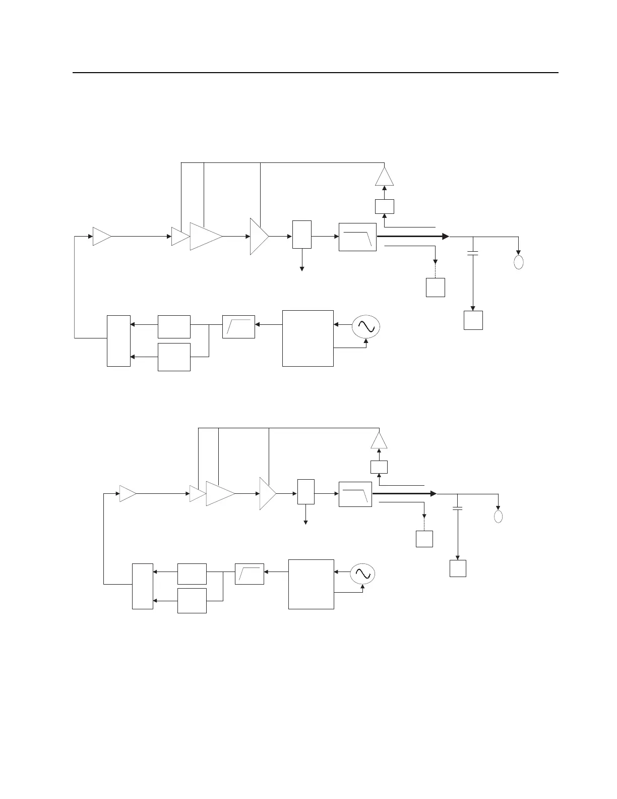
When the radio is transmitting, microphone audio is digitized and then processed by the DSP and
sent to the Trident IC (see Figure 3-7, Figure 3-8 and Figure 3-9) via the SSI interface. The Trident IC
processes the SSI data for application to the voltage controlled oscillator as a modulation signal.
Figure 3-7. Transmitter (UHF1/UHF2) Block Diagram
Figure 3-8. Transmitter (VHF) Block Diagram
Trident IC
Synthesizer
Loop Filter
TX VCO
RX
VCO
RF Switch Matrix
TX Buffer Amp
TX Driver Amplifier
Transmitter Final
FET UHF1/UHF2
Harmonic
LP Filter
Ref. Oscillator
Antenna Connector
Directional
Coupler
Antenna
Switch
TO RX
GPS
Reverse Power
Detection
Log Amp Power Detector
Digital RF Attenuator
Trident IC
Synthesizer
Loop Filter
TX VCO
RX
VCO
RF Switch Matrix
TX Buffer Amp
TX Driver Amplifier
Transmitter Final
FET VHF
Harmonic
LP Filter
Ref. Oscillator
Antenna Connector
Directional
Coupler
Antenna
Switch
TO RX
GPS
Reverse Power
Detection
Log Amp Power Detector
Digital RF Attenuator

 Loading...