Radio Alignment Procedures: Performance Testing 6-21
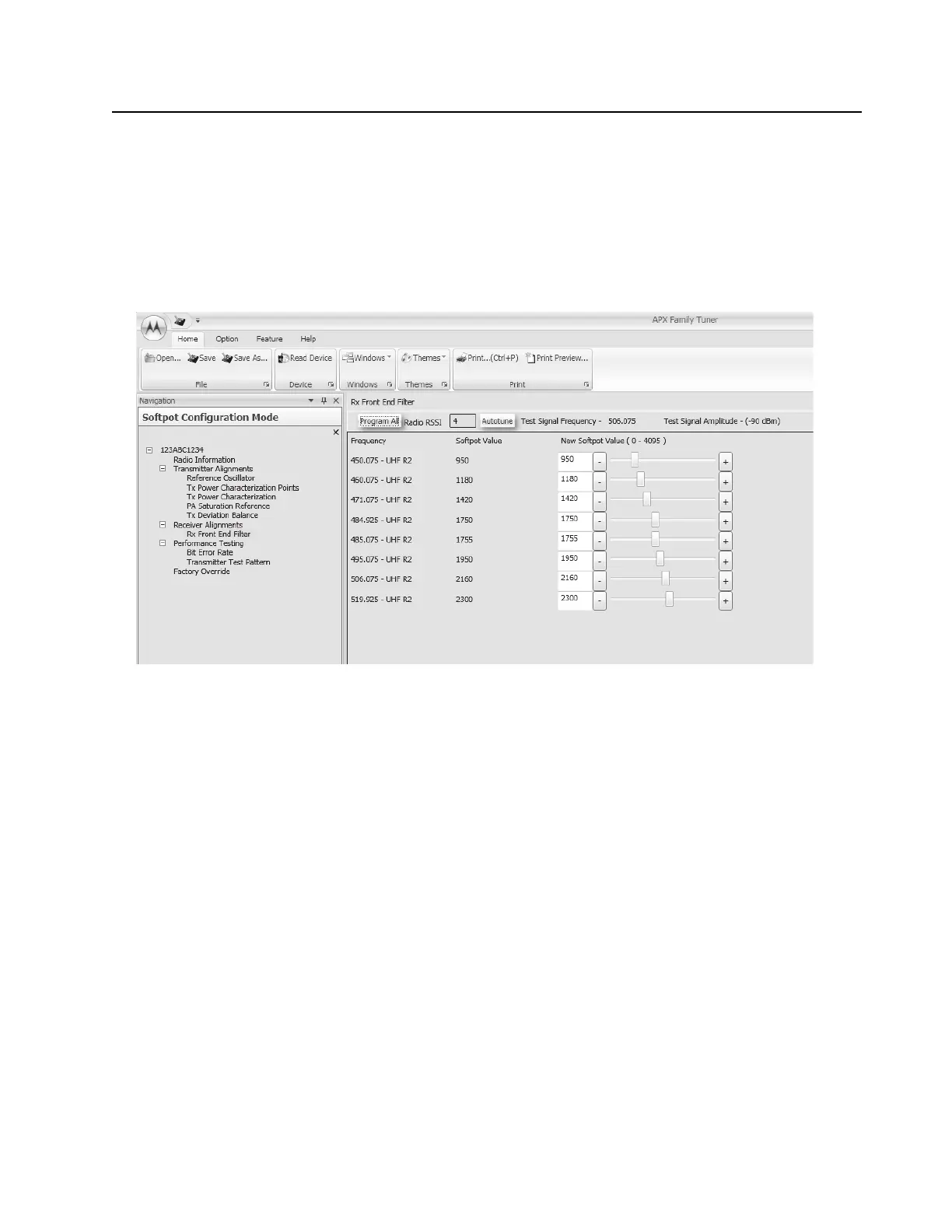
2. Click on the slider or the "New Softpot Value" text box to select which frequency to tune.
3. Apply RF test signal input with no modulation at -90 dBm on the Test Signal Frequency
displayed at the top of the screen.
4. Left-click the Autotune button.
5. Repeat the steps 2 to 4 for all frequencies.
Left-click the Program All button on the screen to save the tuned values in the radio.
Figure 6-26. Front End Filter Alignment Screen (UHF2)
6.7 Performance Testing
6.7.1 Bit Error Rate
This section describes the Bit Error Rate (BER) test of the radio’s receiver at a desired frequency
(see Figure 6-27, Figure 6-28, Figure 6-29, and Figure 6-30).
6.7.1.1 Bit Error Rate Fields
Set up the R2670 Communication Analyzer as follows:
1. Connect the RF Input port of the radio under test to the RF IN/OUT port of the R2670 Service
Monitor.
2. Set up the R2670 Service Monitor:
- In the Display Zone, select PROJ 25 STD mode and set the meter to RF DISPLAY.
- In the RF Zone, configure the analyzer as follows:
RF Control: Generate
Preset: B/W: NB
Freq: Test frequency (Ex: 851.0625 MHz)
Output Level: -50.0 dBm
Gen RF Out: RF I/O

 Loading...