5-4 Performance Checks: Display Radio Test Mode
NOTE: All displays are temporary and will expire without any user intervention. If
information is longer than the physical length of the radio’s display, the information
will wrap around to the next display. After the last display, “RF TEST” is displayed.
NOTE: Press the Top Side Button to advance the test environments from “RF TEST”, “CH
TEST”, “CID TEST” then press the
Top Button to confirm selection. Press any other buttons to advance the test.
Once a test is carried out, restart the radio to proceed to another test.
3. Do one of the following:
•Press the Top Side Button to stop the displays and toggle between RF test mode and the
Control Top test mode. The test mode menu “CH TEST” is displayed, indicating that you
have selected the Control Top test mode. Go to Section CH Test Mode.
NOTE: Each press of the Top Side Button scrolls through “RF TEST”,
“CH TEST” and “CID TEST”.
•Press the Top Button to stop the displays and put the radio into the RF test mode. The
test mode menu, “1 CSQ”, is displayed, indicating test frequency 1
, Carrier SQuelch mode.
Go to Section RF Test Mode.
NOTE: Once your radio is in a particular test mode, you must turn off the radio and turn it
back on again to access the other test mode.
5.2.2 RF Test Mode
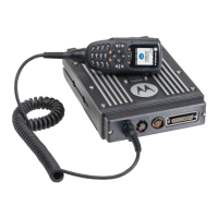
When the ASTRO APX 3000 radio is operating in its normal environment, the radio's microcomputer
controls the RF channel selection, transmitter key-up, and receiver muting, according to the
customer codeplug configuration. However, when the unit is on the bench for testing, alignment, or
repair, it must be removed from its normal environment using a special routine, called RF TEST
MODE.
While in RF test mode:
• Each additional press of Side Button 2 advances to the next test channel. (Refer to Table 5-3.)
•Pressing Side Button 1 scrolls through and accesses the test environments shown in
Table 5-4.
•Pressing Top Side Button scrolls through the Tx Deviation Frequency.
NOTE: Transmit into a load when keying a radio under test.
ESN The radio’s unique electronic serial
number
Always
ROM Size The memory capacity of the host FLASH
part
Always
FLASHcode The FLASH codes as programmed in the
codeplug
Always
RF band 1 The radio’s operating frequency Always
Tuning Ver Version of Tuning codeplug Always
Proc Ver Version of Processor Always
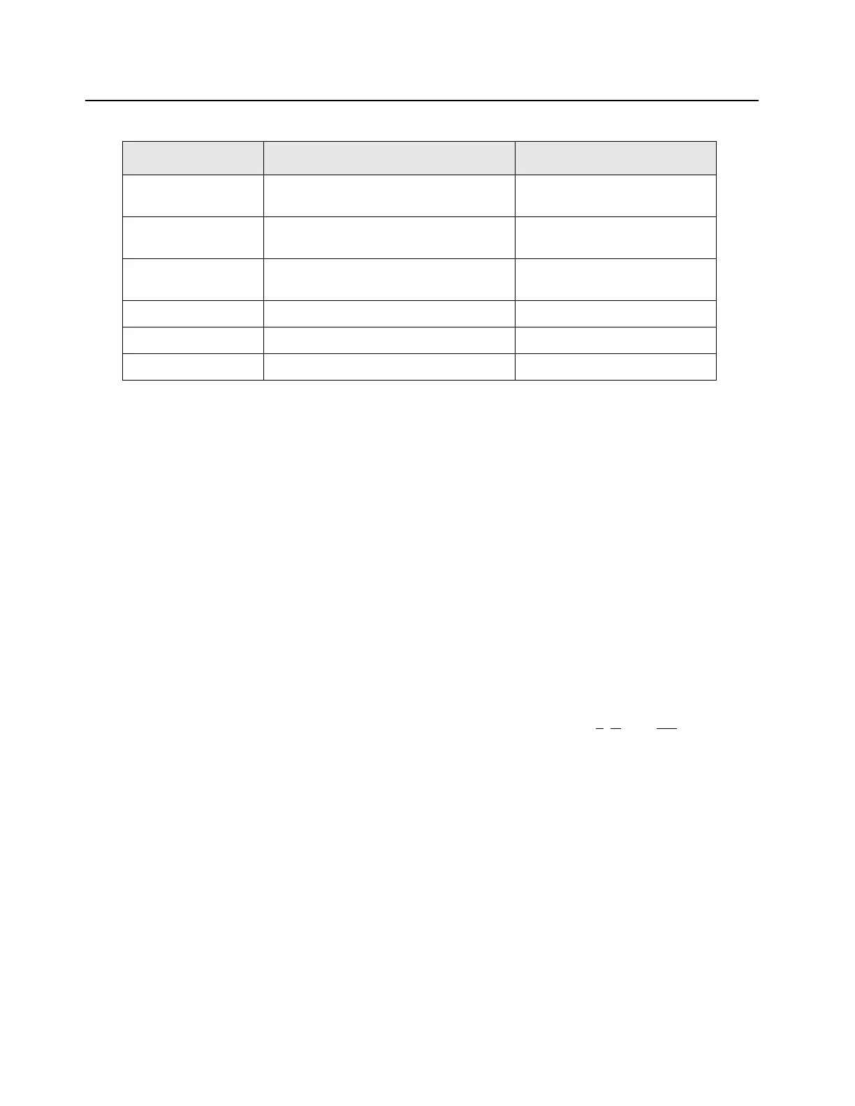
Table 5-2. Test-Mode Displays (Continued)
Name of Display Description Appears

 Loading...