Home
Motorola
Two-Way Radio
APX 3000
Motorola APX 3000 Basic Service Manual
4
of 1
of 1 rating
144 pages
Give review
Manual
Specs
To Next Page
To Next Page
To Previous Page
To Previous Page
Loading...
8-6
Disassembly/Reassembly Proc
edures
: Radio Disa
ssembly
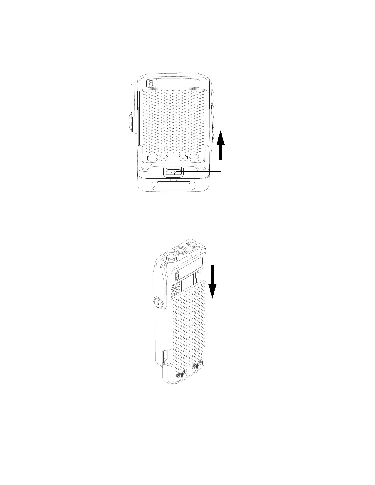
1.
With the radio
turned of
f, lift up
the latch locate
d at the bottom
of the battery
.
Figure 8-4. Lif
ting up the latch
2.
While lifting the latch, remove the battery by sliding it out as sh
own.
Figure 8-
5. Removing
the Batter
y
Battery Latch
Lift up
Slide down
91
93
Table of Contents
Foreword
3
Manual Revisions
3
Product Safety and Rf Exposure Compliance
3
Computer Software Copyrights
3
Document Copyrights
3
Disclaimer
3
Trademarks
3
Document History
5
Table of Contents
7
Commercial Warranty
15
II. General Provisions
15
Limited Warranty
15
Motorola Communication Products
15
What this Warranty Covers and for How Long
15
III. State Law Rights
16
IV. How to Get Warranty Service
16
What this Warranty Does Not Cover
16
VI. Patent and Software Provisions
17
VII. Governing Law
17
Model Numbering, Charts, and Specifications
19
Chapter 1 Introduction
29
Manual Contents
29
Notations Used in this Manual
29
Radio Description
30
Flashport
30
Table 1-1. ASTRO APX 3000 Basic Features
30
Chapter 2 Basic Maintenance
31
General Maintenance
31
Safe Handling of CMOS and LDMOS Devices
31
Chapter 3 Basic Theory of Operation
33
Major Assemblies
33
Figure 3-1. APX 3000 Overall Block Diagram
33
Analog Mode of Operation
34
Figure 3-2. Receiver Block Diagram (UHF1)
34
Figure 3-3. Receiver Block Diagram (UHF2)
34
Figure 3-4. Receiver Block Diagram (VHF)
35
Figure 3-5. Receiver Block Diagram (700/800 Mhz)
35
Figure 3-6. GPS Diagram
35
Figure 3-7. Transmitter (UHF1/UHF2) Block Diagram
37
Figure 3-8. Transmitter (VHF) Block Diagram
37
Figure 3-9. Transmitter (700/800 Mhz) Block Diagram
38
Digital (ASTRO) Mode of Operation
39
Controller Section
39
Figure 3-10. Controller Block Diagram
39
Figure 3-11. Gps/Bluetooth/Accelerometer Block Diagram
41
Chapter 4 Recommended Test Equipment and Service Aids
43
Recommended Test Equipment
43
Table 4-1. Recommended Test Equipment
43
Service Aids
44
Field Programming
44
Table 4-2. Service Aids
44
Chapter 5 Performance Checks
45
Test Equipment Setup
45
Figure 5-1. Performance Checks Test Setup
45
Table 5-1. Initial Equipment Control Settings
46
Display Radio Test Mode
47
Table 5-2. Test-Mode Displays
47
Rf Test Mode
48
Table 5-3. Test Frequencies (Mhz)
49
Table 5-4. Test Environments
49
Receiver Performance Checks
50
Table 5-5. Receiver Performance Checks
50
Table 5-6. Receiver Tests for ASTRO Conventional Channels
51
Transmitter Performance Checks
52
Table 5-7. Transmitter Performance Checks - APX 3000
52
Table 5-8. Transmitter Tests for ASTRO Conventional Channels - APX 3000
53
Chapter 6 Radio Alignment Procedures
55
Test Setup
55
Figure 6-1. Radio Alignment Test Setup
55
Tuner Main Menu
56
Softpot
56
Figure 6-2. Tuner Software Main Menu
56
Figure 6-3. Typical Softpot Screen
57
Radio Information
58
Transmitter Alignments
58
Figure 6-4. Radio Information Screen
58
Reference Oscillator Alignment
58
Figure 6-5. Reference Oscillator Alignment Screen (UHF1)
59
Figure 6-6. Reference Oscillator Alignment Screen (UHF2)
60
Figure 6-7. Reference Oscillator Alignment Screen (VHF)
60
Figure 6-8. Reference Oscillator Alignment Screen (700/800 Mhz)
61
Table 6-1. Reference Oscillator Alignment
62
Figure 6-9. Transmit Power Characterization Points Alignment Screen (UHF1)
62
Figure 6-10. Transmit Power Characterization Points Alignment Screen (UHF2)
63
Figure 6-11. Transmit Power Characterization Points Alignment Screen (VHF)
63
Figure 6-12. Transmit Power Characterization Points Alignment Screen (700/800Mhz)
64
Figure 6-13. Transmit Power Characterization Alignment Screen (UHF1)
66
Figure 6-14. Transmit Power Characterization Alignment Screen (UHF2)
66
Figure 6-15. Transmit Power Characterization Alignment Screen (VHF)
67
Figure 6-16. Transmit Power Characterization Alignment Screen (700/800 Mhz)
67
Figure 6-17. PA Saturation Referencing Alignment Screen (UHF1)
68
Figure 6-18. PA Saturation Referencing Alignment Screen (UHF2)
69
Figure 6-19. PA Saturation Referencing Alignment Screen (VHF)
69
Figure 6-20. PA Saturation Referencing Alignment Screen (700/800 Mhz)
70
Figure 6-21. Transmit Deviation Balance Alignment Screen (UHF1)
72
Figure 6-22. Transmit Deviation Balance Alignment Screen (UHF2)
72
Figure 6-23. Transmit Deviation Balance Alignment Screen (VHF)
73
Figure 6-24. Transmit Deviation Balance Alignment Screen (700/800 Mhz)
73
Front End Filter Alignment
74
Figure 6-25. Front End Filter Alignment Screen (UHF1)
74
Performance Testing
75
Figure 6-26. Front End Filter Alignment Screen (UHF2)
75
Figure 6-27. Bit Error Rate Screen (UHF1)
77
Figure 6-28. Bit Error Rate Screen (UHF2)
77
Figure 6-29. Bit Error Rate Screen (VHF)
78
Figure 6-30. Bit Error Rate Screen (700/800 Mhz)
78
Figure 6-31. Transmitter Test Pattern Screen (UHF1)
79
Figure 6-32. Transmitter Test Pattern Screen (UHF2)
80
Figure 6-33. Transmitter Test Pattern Screen (VHF)
80
Figure 6-34. Transmitter Test Pattern Screen (700/800 Mhz)
81
Chapter 7 Encryption
83
Load an Encryption Key
83
Table 7-1. Kit Numbers for Secure-Enabled Boards
83
Multikey Feature
84
Select an Encryption Key
84
Erase an Encryption Key
84
Chapter 8 Disassembly/Reassembly Procedures
87
APX 3000 Exploded View (Main Subassemblies)
87
Table 8-1. APX 3000 Partial Exploded View Parts List
88
Figure 8-1. APX 3000 Partial Exploded View
88
Required Tools and Supplies
89
Fastener Torque Chart
89
Table 8-2. Required Tools and Supplies
89
Table 8-3. Required Tools and Supplies
89
Radio Disassembly
90
Figure 8-2. Removing the Thumb Screw
90
Figure 8-3. Removing the Antenna
91
Figure 8-4. Lifting up the Latch
92
Figure 8-5. Removing the Battery
92
Figure 8-6. Disengage the Chassis
93
Figure 8-7. Remove the Chassis Assembly
93
Figure 8-8. Remove the Chassis Screws
94
Figure 8-9. Remove the Secondary Shield Assembly
94
Figure 8-10. Remove the Main O-Ring at the Antenna Holder
95
Figure 8-11. Lift up the Main Board from the Chassis
95
Serviceable Components of the Main Sub-Assemblies
96
Figure 8-12. Remove Battery Seal
96
Figure 8-13. Serviceable Components - Main Board Assembly
96
Figure 8-14. Serviceable Components - Chassis Assembly
97
Table 8-4. Serviceable Components
98
Figure 8-15. Serviceable Components - Main Housing
100
Radio Reassembly
101
Figure 8-16. Assemble the Battery Seal
101
Figure 8-17. Assemble the Main O-Ring at Antenna Holder
101
Figure 8-18. Assemble the RF Board
102
Figure 8-19. Assemble the Secondary Shield Assembly
102
Figure 8-20. Torque in the Chassis Screws
103
Figure 8-21. Slide Chassis Assembly into Front Housing
103
Figure 8-22. Assemble Back Kit and Front Kit Together
104
Figure 8-23. Engaging Hook and Seating Cover
104
Figure 8-24. Securing the Cover
105
Figure 8-25. Attaching the Antenna
105
Figure 8-26. Assemble the Seal, Vacuum Port
106
Figure 8-27. Assemble the Label Gore Port
106
Figure 8-28. Assemble the Bottom Label
107
Figure 8-29. Attaching Battery - Slide into Position
107
Ensuring Radio Submergibility
108
Figure 8-30. Attaching Vacuum Test Fixture
110
Battery Contact Seal
112
Troubleshooting Leak Areas
112
Chapter 9 Basic Troubleshooting
113
Power-Up Error Codes
113
Table 9-1. Power-Up Error Code Displays
113
Operational Error Codes
114
Receiver Troubleshooting
114
Table 9-2. Operational Error Code Displays
114
Table 9-3. Receiver Troubleshooting Chart
114
Transmitter Troubleshooting
115
Table 9-4. Transmitter Troubleshooting Chart
115
Encryption Troubleshooting
116
Table 9-5. Encryption Troubleshooting Chart
116
Chapter 10 Exploded Views and Parts Lists
117
Table 10-1. APX 3000 Exploded Views and Controller Kit
117
10.1 APX 3000 Front Kit Exploded View
118
Figure 10-1. APX 3000 Front Kit Exploded View
118
10.2 APX 3000 Front Kit Exploded View Parts List
119
10.3 APX 3000 Back Kit Exploded View
120
Figure 10-2. APX 3000 Back Kit Exploded View
120
10.4 APX 3000 Back Kit Exploded View Parts List
121
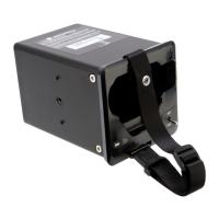
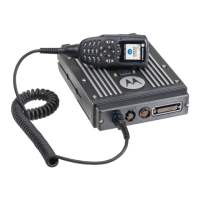
Appendix A Accessories
123
Appendix B Replacement Parts Ordering
125
Basic Ordering Information
125
Transceiver Board Ordering Information
125
Motorola Online
125
Mail Orders
125
Telephone Orders
126
Fax Orders
126
Parts Identification
126
Product Customer Service
126
B.5 Telephone Orders
126
Glossary
127
Other manuals for Motorola APX 3000
User Guide
104 pages
Quick Reference Guide
44 pages
Quick Reference Card
92 pages
Detailed Service Manual
474 pages
4
Based on 1 rating
Ask a question
Give review
Questions and Answers:
Need help?
Do you have a question about the Motorola APX 3000 and is the answer not in the manual?
Ask a question
Motorola APX 3000 Specifications
General
Brand
Motorola
Model
APX 3000
Category
Two-Way Radio
Language
English
Related product manuals
Motorola APX 3
48 pages
Motorola APX 8000 3
202 pages
Motorola APX 8500
273 pages
Motorola APX 7500
70 pages
Motorola APX 6000
200 pages
Motorola APX 4500
201 pages
Motorola APX 6500
52 pages
Motorola APX 8000
161 pages
Motorola APX 1000
166 pages
Motorola APX NEXT
119 pages
Motorola ASTRO APX
168 pages
Motorola APX Mobile
146 pages

 Loading...