REFRIGERATION DIVISION
V SERIES
SCREW COMPRESSOR HANDLING MANUAL
Supersedes all previous version. This information is for reference use only and subject to change without notice
Revision 2 (June 05,2000) Page 10 of 61
f) Next, record the position of operation start (confirm the position of the stamp on the screw
head).
Turn the Vi changing rod counterclockwise the number of rotations indicated for the particular
compressor as given in Fig. 13.
After adjusting, secure the lock nut (approx. 1/12 of a turn after contact with the casing). When
securing the lock nut, be sure that the Vi changing rod does not rotate out of position.
g) Set the capacity control mechanism to the full load position.
If the needle pointer of the capacity control indicator indicates the specified porti range on the
dial, proper adjustment is confirmed.
An amplitude is provided between the M and H graduations on the indicator dial because the
M and H positions shift depending on whether the compressor is a 160SML, 200 SML or 250
SML model as well as on the rotor length, of which there are nine. Since the graduations on
the dial are common to all models, an amplitude is provided. When the Vi changing rod is
adjusted the correct number of turns and the needle pointer position is within the specified
range, adjustment can be considered correct.
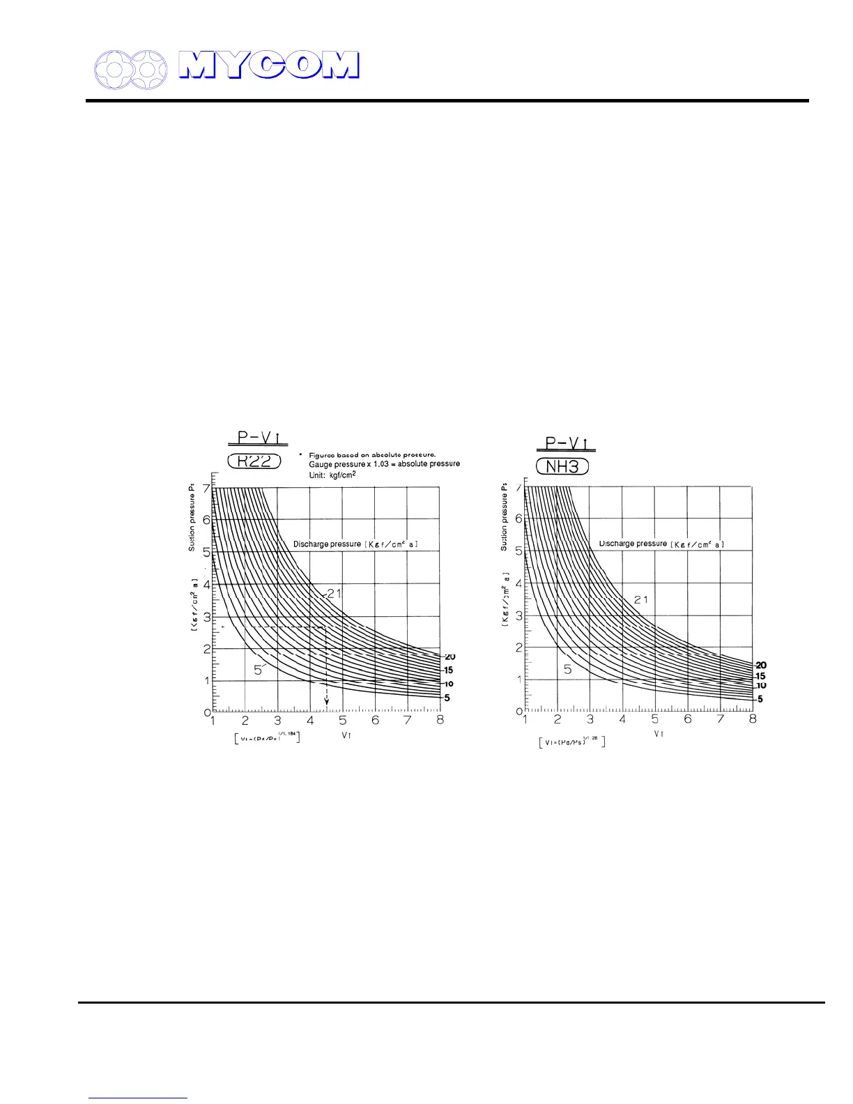
Fig. 12 Graphs for determining Vi from Operating Suction and Discharge Pressure (R22, NH
3
)
h) Secure the hex head cap nut (453) for the Vi changing rod securely (rotate approx. 1/12 turn
after contacting casing).

 Loading...
