REFRIGERATION DIVISION
V SERIES
SCREW COMPRESSOR HANDLING MANUAL
Supersedes all previous version. This information is for reference use only and subject to change without notice
Revision 2 (June 05,2000) Page 41 of 61
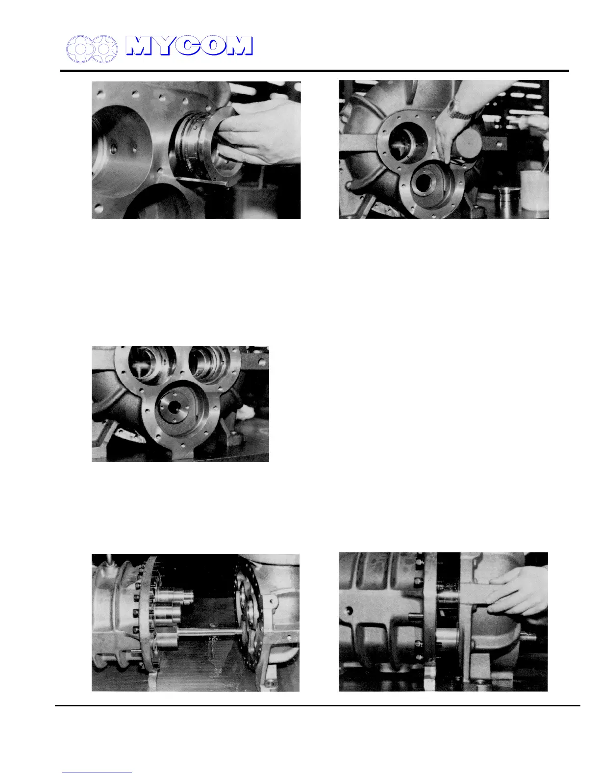
Fig. 79 Positioning Side Bearing (28) Fig. 80 Mounting
b) Secure the stop ring.
c) Mount the O-ring retainer (326) for the unloader push rod. The suction cover side also requires
an O-ring so do not forget to mount during the assembly work.
d) Mount the balance piston sleeve in the order of stop ring (32), O-ring retainer (36), O-ring (35),
balance piston sleeve (33) and stop ring (32).
When installing the stop ring, tap the side face slightly to ensure that it fits snugly in the
groove.
Fig. 81 O-Ring Retainer (36)
e) Secure the balance piston sleeve (33) with the hex-head socket detent set screw (34) from the
female rotor side.
f) Turn the Vi changing rod (444) in the rotor casing/bearing head assembly in the
counterclockwise direction to set the Vi to the L port position. Set the unloader slide valve (54)
at the full load position.
Fig. 82 Fitting Suction Cover Fig. 83 Suction Cover Assembled

 Loading...
