REFRIGERATION DIVISION
V SERIES
SCREW COMPRESSOR HANDLING MANUAL
Supersedes all previous version. This information is for reference use only and subject to change without notice
Revision 2 (June 05,2000) Page 30 of 61
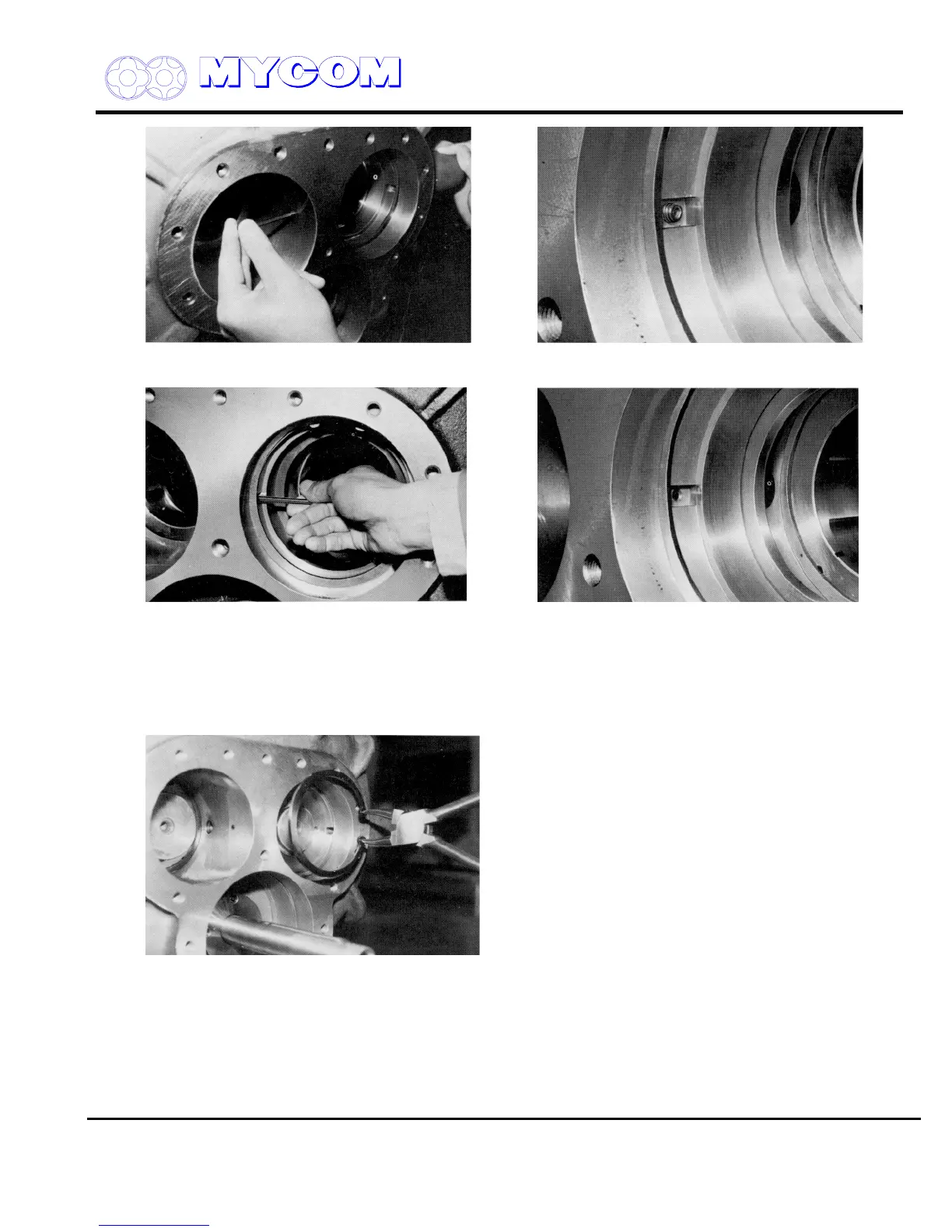
Fig. 43 Loosening Balance Piston Sleeve Detent Fig. 44 Balance Piston Sleeve Set Screw Portion
Screws (74)
Fig. 45 Screwing in Position Detent Pin (34) Fig. 46 After Screwing in Positioning Detent Pin (34)
d) Pull out the balance piston sleeve. This is easily accomplished as the sleeve is fitted with
some clearance.
Now remove the O-ring (35) and O-ring retainer (36).
e) If you plan to remove the side bearing (28) also, at this time remove the inside stop ring (29).
Fig. 47 Removing Stop Ring (29)
3.4.6.2 Inspection
Since the clearance between the balance piston (30) and the balance piston sleeve (33) is smaller
than the clearance between the rotor shaft and the bearing, the sleeve (33) may experience wear.
If the sleeve dimensions exceed the service limits indicated at the end of this manual, replace the
sleeve. The clearance provided on the periphery of the balance piston is designed to be adjusted by

 Loading...
