REFRIGERATION DIVISION
V SERIES
SCREW COMPRESSOR HANDLING MANUAL
Supersedes all previous version. This information is for reference use only and subject to change without notice
Revision 2 (June 05,2000) Page 25 of 61
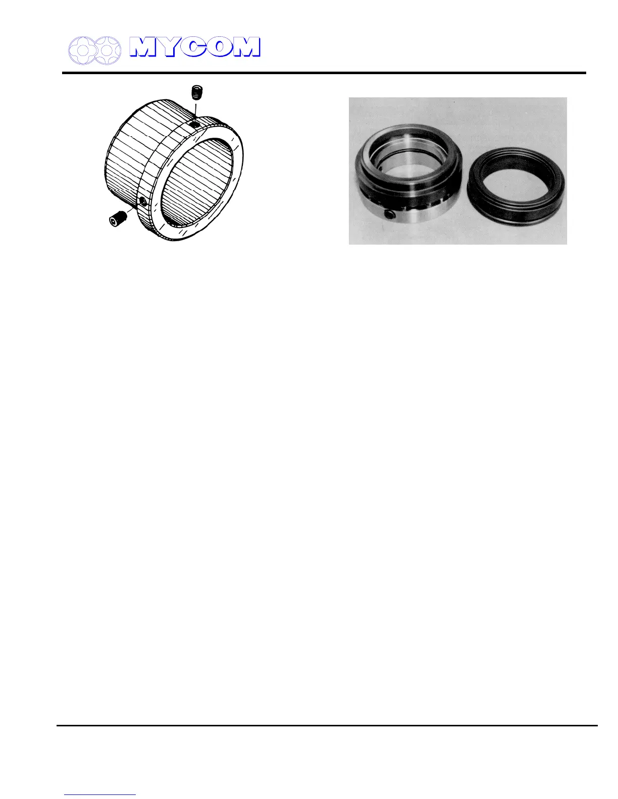
Fig. 27A Oil Seal Sleeve Fig. 27B Shaft Seal Assembly
3.4.1.2 Inspection
a) Inspect the frictional surfaces of the carbon and seal ring (104). A carbon with a smooth,
unblemished face can be reused but if there are any signs of damage or peeling, replace the
carbon, otherwise oil leakage may result.
b) Inspect the O-rings. With Freon refrigerant systems, the O-rings may suffer from swelling or
deformation. If any abnormality is observed in an O-ring, replace it. A total of four O-rings are
used for the seal cover, seal carbon and seal collar.
c) Inspect the frictional surface of the oil seal sleeve (528). If any wear is found, replace the oil
seal and the sleeve with new parts. Since the oil seal is specially designed for the compressor,
only genuine parts should be used.
d) If the seal cover gasket (527) proves difficult to remove when the seal is being disassembled,
replace with a new one.
3.4.2 Unloader Indicator
The unloader indicator shows the position of the unloader slide valve (54) based on conversion of the
angle of rotation of the cylinder cam (77) to an electric signal. Two types of unloader indicator are
available. One is a contact resistance potentiometer type and the other is a non-contact electronic
type. Both are used for the same purpose as a rule. An explosion-proof indicator is also available as
an option for special applications.
3.4.2.1 Removing Unloader Indicator Assembly
When disassembling the compressor, the unloader indicator should be removed as an assembly.
a) Detach the wiring to the unloader indicator and remove the three hex-head (147) securing the
indicator cover (146)
b) The indicator cover, glass (141) and glass spacer (142) can now be removed. Be careful not to
drop the glass or glass spacer.
c) The micro-switch cam (127) or coupling which connects the potentiometer or magnetic
turntable and cylinder cam is located on the unloader cover side. Loosen the fixing screws
(128) to free the cylinder cam.

 Loading...
