REFRIGERATION DIVISION
V SERIES
SCREW COMPRESSOR HANDLING MANUAL
Supersedes all previous version. This information is for reference use only and subject to change without notice
Revision 2 (June 05,2000) Page 29 of 61
3.4.6 Balance Piston (30) and Balance Piston Sleeve (33)
With screw compressors the male rotor is subjected to strong thrust load from the discharge side and
rotates considerably faster than the female rotor. If the same type of thrust bearing were used for both
the male and female rotors, the male side bearing life would be much shorter.
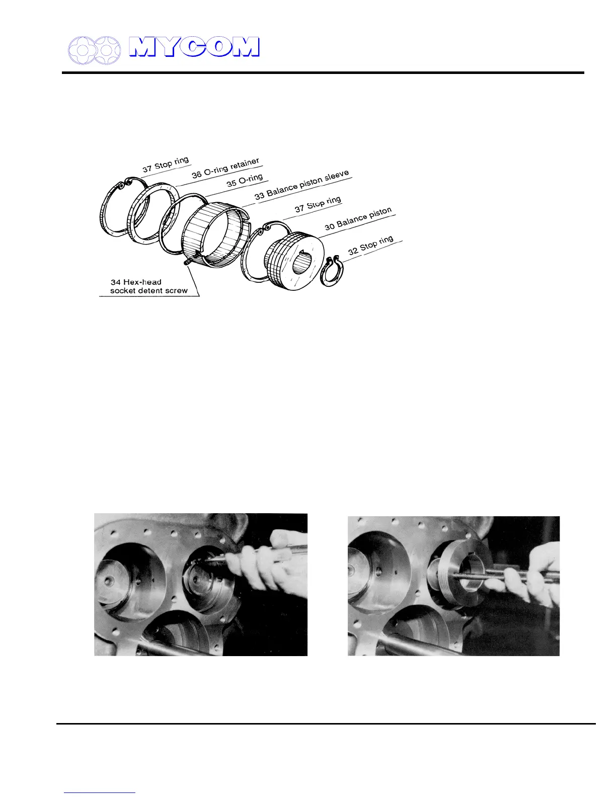
Fig. 40 Exploded View of Balance Piston
A piston (30) is provided on the end of the drive shaft of the male rotor to offset thrust load
hydraulically. This piston is commonly called the balance piston.
The clearance between the balance piston and the sleeve is extremely small (smaller than the
clearance between the bearing and the shaft) in order to prevent oil leakage.
3.4.6.1 Disassembly
a) Remove the stop ring (32), which secures the balance piston (30) to the shaft using a pair of
pliers. Screw an eyebolt into the hole in the balance piston and pull out parallel to the shaft.
The balance piston key (31) will remain in the keyway. Leave the key as is.
b) Hex-head socket set screws (34) are screwed into both sides to prevent rotation of the
balance piston sleeve (33).
Loosen the F side screw and remove the M side screw or screw in until the head is recessed
in the suction cover.
Fig. 41 Removing Stop Ring Fig. 42 Pulling out Balance Piston (30)
c) Remove the balance piston sleeve stop ring (37).
Since the O-ring (35) pushes on the stop ring (37), it can easily be removed by pushing on the
sleeve (33).

 Loading...
