REFRIGERATION DIVISION
V SERIES
SCREW COMPRESSOR HANDLING MANUAL
Supersedes all previous version. This information is for reference use only and subject to change without notice
Revision 2 (June 05,2000) Page 38 of 61
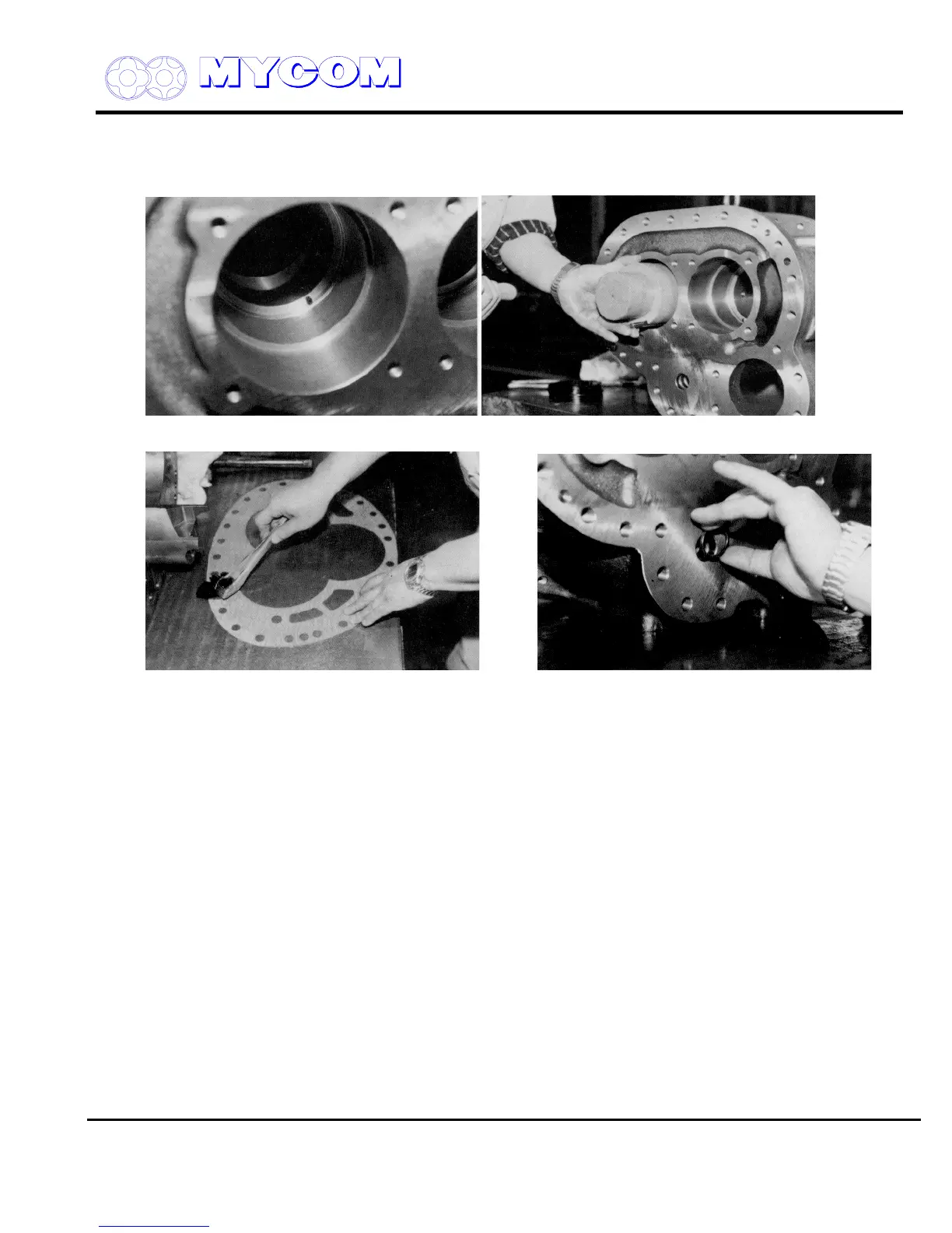
d) Apply oil to both sides of the gasket before fitting it between the bearing head and rotor
casing. Since the positions of the holes in the gasket are unsymmetrical, care should be taken
to position the gasket correctly.
Fig. 65 Bearing Positioning Spring Pin (14) Fig. 66 Fitting Bearing
Fig. 67 Applying Oil to Gasket Fig. 68 O-Ring for V
i
Changing Rod (451)
4.2 Rotor Casing (1), Unloader Slide Valve (54), Variable Vi Slide Valve (289) and Bearing Head (11)
a) Unloader slide valve (54)
Confirm that the Vi changing rod (444) moves properly. Mount the unloader push rod (67) and
fit the gasket to the hole for the Vi changing rod shaft.
b) Rotor casing (1)
Clean the oil injection holes thoroughly, fit the plug (10) and mount the unloader slide valve
(54). Confirm smooth movement of the unloader slide valve.
c) If the rotor casing (1) and bearing head (11) have been separated, assemble them now
(normally, these two parts are not disassembled). Tighten the bolts (2) to the specified torque
in a symmetrical crisscross pattern. A number of the bolts on the bottom cannot be accessed
at this time and must be tightened later when the compressor is raised.

 Loading...
