REFRIGERATION DIVISION
V SERIES
SCREW COMPRESSOR HANDLING MANUAL
3.4.3.2 Inspection
a) If the indicator is not actuating normally, check the cylinder cam groove, bearing and slotted
pin (unloader push set side) for abnormality.
b) If there is refrigerant or oil leakage, replace the Teflon V-ring (82).
In such a case, the shaft seal portion of the cylinder cam (77) should be disassembled
according to the following procedures.
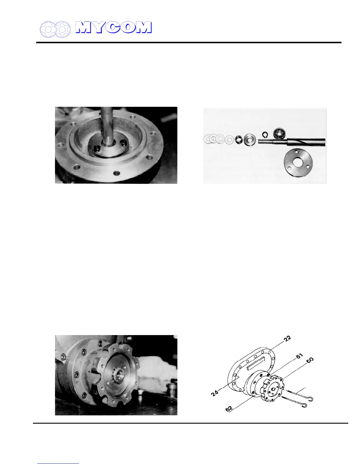
Fig. 34 Cylinder Cam Mounting Portion Fig. 35 Unloader Indicator Cam Shaft Portion
1) A bearing gland (80) provided at the unloader cover cylinder side secures the cylinder cam
(77). Remove the bearing gland (80) by loosening and removing the hex-head cap screws
(81).
2) The cylinder cam (77), ball bearing (78) and stop ring (79) can now be removed together. If the
cylinder cam and ball bearing are to be replaced, remove the stop ring first and replace the
cylinder cam and ball bearing.
3) A spring retainer (84), spring (83) and Teflon V-ring assembly (82) are fitted inside the cover.
4) Check the packing and the groove in the cylinder cam for damage or abnormal wear and
replace if necessary.
3.4.4 Unloader Piston (64) and Unloader Cylinder (60)
3.4.4.1 Disassembly
a) Pull out the unloader piston to the full load position. If the Vi is adjusted to the H port, the
unloader piston will stop a bit closer than otherwise.
Straighten the claws of the lock washer (70) on the lock nut (69) securing the piston (64) to the
push rod (67).
Supersedes all previous version. This information is for reference use only and subject to change without notice
Revision 2 (June 05,2000) Page 27 of 61
Fig. 36 Piston Lock Nut (69) Fig. 37 Pulling out Unloader Piston (64)

 Loading...
