REFRIGERATION DIVISION
V SERIES
SCREW COMPRESSOR HANDLING MANUAL
Supersedes all previous version. This information is for reference use only and subject to change without notice
Revision 2 (June 05,2000) Page 45 of 61
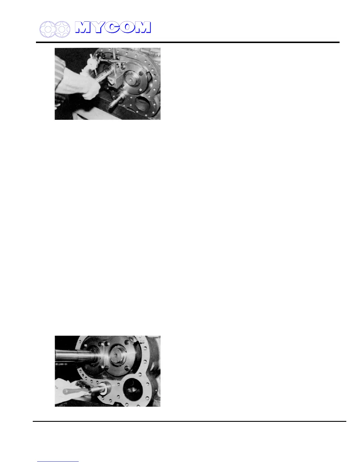
Fig. 91 Determining Axial Deflection
l) Next, check the axial deflection of shaft rotation with the dial indicator positioned on the oil
seal fitting portion.
Maximum deflection of the 0.015 mm is acceptable.
Deflection may be cause by no uniformity of the thrust adjusting washer or mismatching of the
stamped bearing parts. Even if the end clearance is within the specified value, disassembly
and adjustment by changing the relative positions of the gland, thrust adjusting washer and
bearing will be necessary. Accurate assembly of the bearing parts is vital for the long life and
maximum performance of the compressor. If dust is caught between the parts, the deflection
value will increase.
m) After completing end clearance adjustment, tighten the thrust bearing securely.
Notes:
1) Always use new lock nuts (39) and lock washers (40).
2) Be sure to position the shim between the lock nut (39) and the lock washer (40).
3) Tighten the lock nuts securely.
Specified torque values are shown in the table in paragraph i)-(1) above. At the plant site, however, it
may be necessary to use a hammer to tighten the nuts if a torque meter is not available. Take the
utmost care to ensure that neither the lock nut nor lock washers are damaged.
4) When tightening the lock nut, mesh the lock nut and the claw of the lock washer and tighten the nut
carefully to the specified torque value. Do not turn the nut counter-clockwise. After the necessary
tightening torque is confirmed, bend the claw of the lock washer. The corners of the thrust bearing hex-
head bolt lock washer (46) should also be bent back to lock.
4.6 Bearing Cover (16)
a) Fit the thrust washer (446) on the Vi changing rod (444).
Fig. 92 Vi Changing Rod and Thrust Washer

 Loading...
