REFRIGERATION DIVISION
V SERIES
SCREW COMPRESSOR HANDLING MANUAL
Supersedes all previous version. This information is for reference use only and subject to change without notice
Revision 2 (June 05,2000) Page 26 of 61
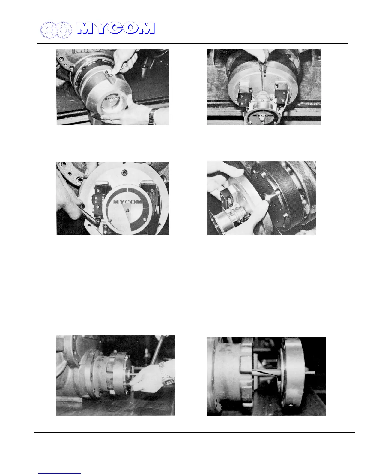
Fig. 28 Removing Indicator Cover Fig. 29 Micro-switch Cam (127) and Coupling fixing
screws (128)
d) Remove all of the hex socket head cap screws (122) securing the micro-switch base plate
(121) to the unloader cover.
Fig. 30 Loosening Micro-switch set plate screws Fig. 31 Removing Micro-switch Assembly
e) Draw out the unloader indicator parallel to the cylinder cam.
3.4.3 Unloader Cover (74)
The cylinder cam (77), shaft bearing (78) and seal are mounted in the unloader cover (74) provided at
the end of the unloader cylinder (60). It is not necessary to disassemble these parts unless there is
some abnormality (e.g., seal leakage or cylinder cam groove wear).
3.4.3.1 Disassembly
a) Remove the hex-head cap screws (76) securing the unloader cover (174) to the cylinder (60).
b) The cylinder cam (77) fixed to the cover is fitted in the bore of the unloader push rod (67) and
the cam groove mates with the push rod pin. Pull of the cover parallel to the cylinder center.
Fig. 32 Removing Unloader Cover Bolts Fig. 33 Unloader Cover (74) and Cylinder Cam (77)

 Loading...
