REFRIGERATION DIVISION
V SERIES
SCREW COMPRESSOR HANDLING MANUAL
5.3 Assembly and Adjustment
The procedures for reassembling the unloader indicator are the reverse of disassembly.
Adjustment after assembly is, of course, very important. There are basically two aspects of
adjustment.
1) The physical relationship between the micro-switch cam (127) and the slide valve (54).
2) The relationship between the no-load position and the resistance value of the potentiometer.
Adjustment of these factors should be carried out after the micro-switch base plate (121) has been
mounted on the unloader cover (74).
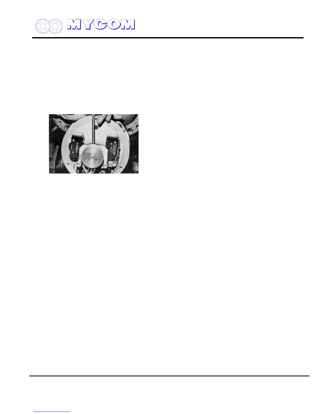
Fig. 111 No-Load Cam Adjustment
a) The unloader cover is fitted on the compressor with the unloader piston (64) in the no-load
position. Secure the micro-switch cam with the hex-head socket head set screw (128) to bring
it into line with the countersunk hole in the unloader indicator cylinder cam (77). The micro-
switch cam (127) is then in the no-load position.
Align the concave point of the micro-switch cam (127) facing the unloader cover (47) with the
actuation arm point of the micro-switch (ref. “A” and “B” in Fig. 110).
b) When mounting the potentiometer (129), fit the spring pin (214) of the potentiometer shaft in
the groove of the shaft support (2) (135) (ref. Figs. 113,114).
c) Correct positioning of the potentiometer is established by the work indicated in the above
paragraph b).
d) Fit the dial plate and mount the indicator pointer (139), aligning it to the no-load position.
If a full load micro-switch is provided, adjust the micro-switch setting screw (126) so that it is
actuated by the cam.
Actuation of the micro-switch (125) is confirmed by moving the unloader slide valve (54) to the
full load position with oil pressure when the hydraulic pump can be operated or by supplying
low-pressure air to the unloader piston (64).
If the machine screws (126) of the micro-switch are loose, the micro-switch may slip out of
position, resulting in irregular or faulty actuation. Secure the micro-switch tightly after
confirming actuation.
e) After confirming proper actuation, connect the control wiring as before and mount the unloader
indicator cover (146). Be careful not to pinch the wires with the cover.
Disassembly, inspection and reassembly of the V-Series compressor unit are now completed.
Supersedes all previous version. This information is for reference use only and subject to change without notice
Revision 2 (June 05,2000) Page 53 of 61

 Loading...
