REFRIGERATION DIVISION
V SERIES
SCREW COMPRESSOR HANDLING MANUAL
Supersedes all previous version. This information is for reference use only and subject to change without notice
Revision 2 (June 05,2000) Page 42 of 61
g) Slide the suction cover across the surface plate and align the suction cover O-ring retainer
with the push rod (67)
h) Mate the side bearing (28) and rotor shafts and push the cover and casing together parallel
with the shaft.
i) Drive the positioning parallel pin (19) in from the rotor casing side and secure the bolts (94).
j) Confirm that the unloader slide valve (54) and variable Vi slide valve (289) move normally.
Rotate the male rotor shaft to confirm smooth movement.
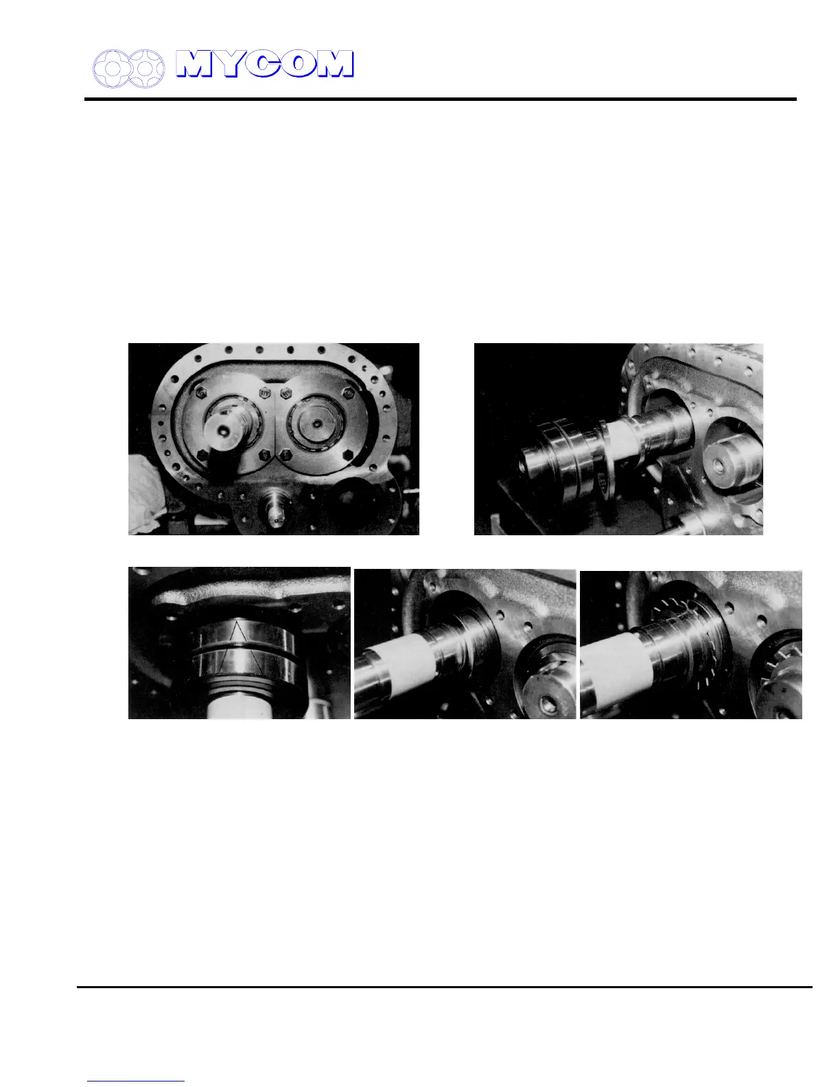
4.5 Thrust Bearing (38)
a) Confirm the M and F stamps on the thrust adjusting washers (42) and mount the thrust
bearings in the casing in the same direction as before disassembly.
Fig. 84 Thrust Bearing Mounting Side Fig. 85 Mounting Order of Thrust Bearing (38)
Fig. 86 Mounting Direction Fig. 87 Thrust Washer Fig. 88 Spacer
b) Care should be taken to exclude any foreign matter or dust particles from the space between
the thrust bearing gland (41) and the adjusting washer (42).
c) The thrust bearing should be installed with the point of the “V” mark inscribed on the bearing
pointed in toward the rotor side (refer to Fig. 86). If the thrust bearing is inserted with the “V”
pointing in the opposite direction, end clearance will differ from that before disassembly
because of the different sizes of the outer and inner race side surfaces.
d) Be sure that the mounting order is correct.
If the lock washer claw is bent at the same point as before, the claw may break. For this
reason it is best to replace the lock washer (40) with a new one. If new washers are not
available, exchange the washers of the male and female rotors.
e) Fix the inner race of the thrust bearing to the rotor using the lock nut.

 Loading...
