REFRIGERATION DIVISION
V SERIES
SCREW COMPRESSOR HANDLING MANUAL
Supersedes all previous version. This information is for reference use only and subject to change without notice
Revision 2 (June 05,2000) Page 48 of 61
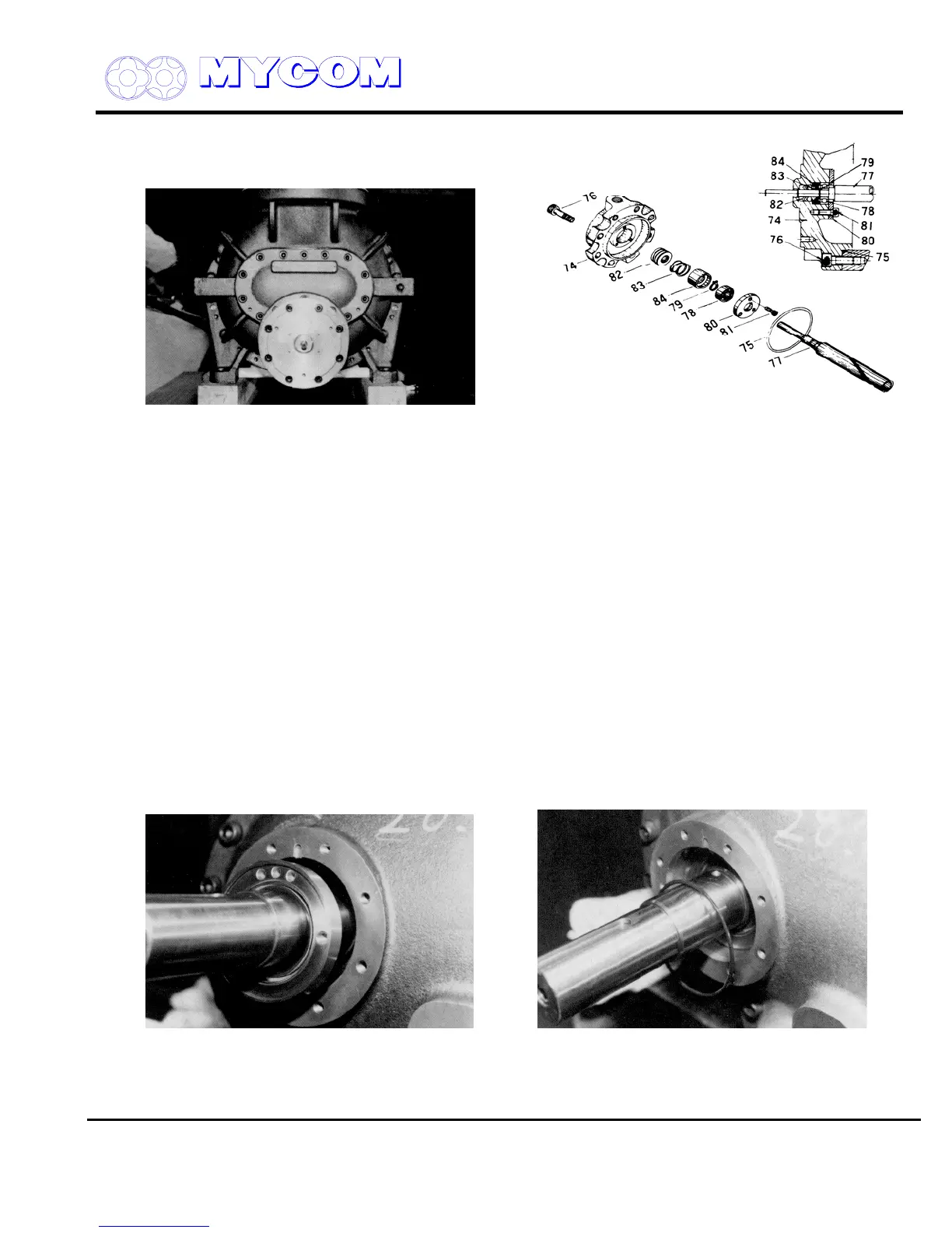
Fig. 99 Mounting Unloader Cover Fig. 100 Exploded View of Unloader Cover (74)
d) Rotate the cylinder cam (77) manually to confirm smooth rotation.
Fit the O-ring (75) on the unloader cover (74).
e) Position the unloader slide valve (54) in the no-load position (piston at the innermost point)
and push in the cover while mating the groove on the cylinder cam with the pin on the push
rod (67).
Fasten the screws (76) with the outlet of the unloader piston hydraulic piping facing up (ref.
Fig.100).
4.9 Mechanical Shaft Seal
a) Clean the contact surface of the shaft seal thoroughly before assembling.
b) Carefully inspect the seal contact surface on the stepped portion of the shaft for flaws and
scratches before assembling.
c) When mounting the seal retainer (48), confirm that it is positioned in the correct direction.
Position the seal retainer so that the oil induction hole is located above the shaft. Be sure that
the seal retainer detent screw (529) and the notch in the retainer are correctly mated and turn
the seal retainer to the left and right using an eye bolt to confirm that it is securely fixed.
Fig. 101 Seal Retainer (48) and Oil Seal Fig. 102 O-Ring (49)
d) Next, insert the seal cover O-ring (49). Note that this part is sometimes forgotten during
assembly.

 Loading...
