REFRIGERATION DIVISION
V SERIES
SCREW COMPRESSOR HANDLING MANUAL
3.3.3 Raising and Removing Compressor
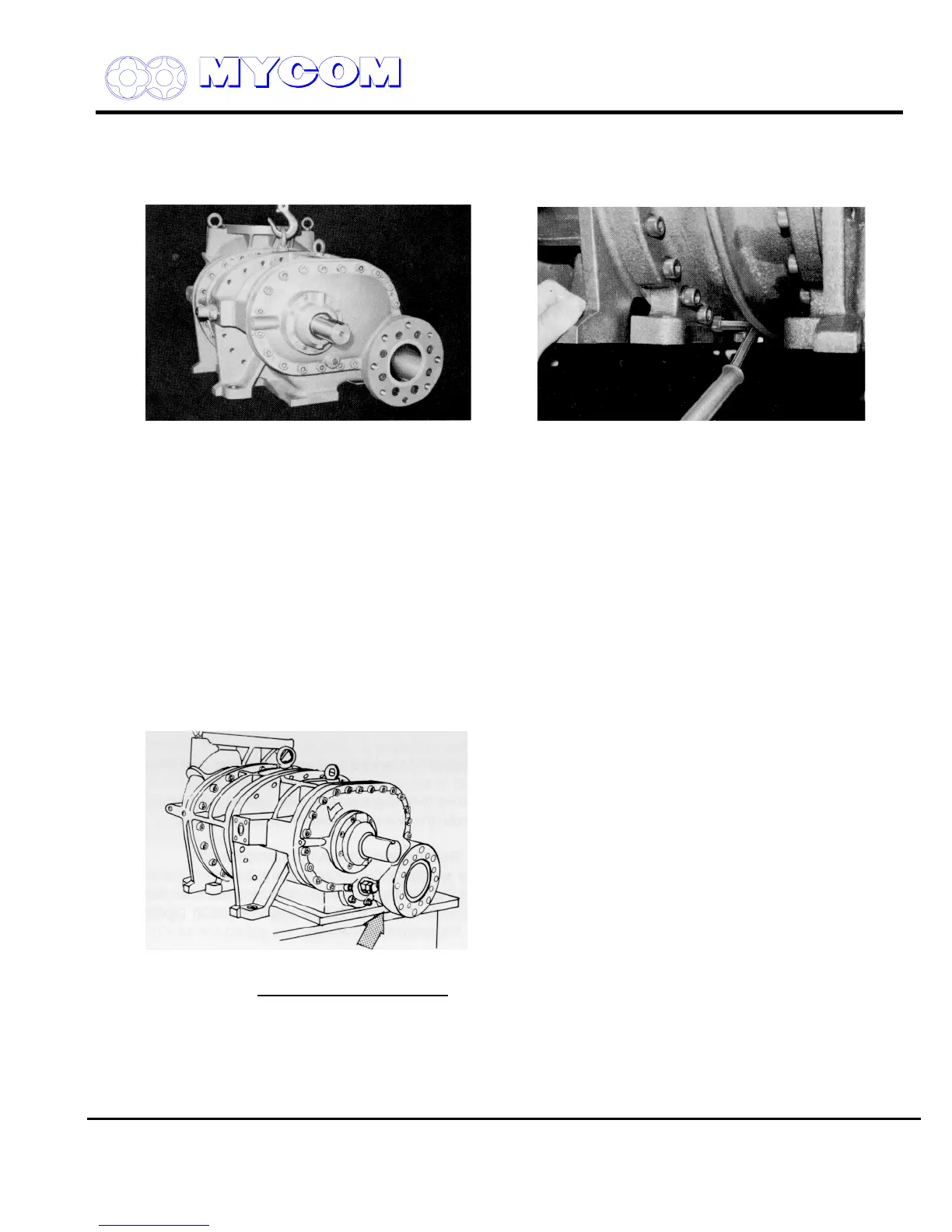
The weight of the suction piping bears on the suction port of the compressor. After removing the bolts
securing the pipe to the port, suspend the suction piping and cover the suction port flange.
Fig. 18 Lifting the Compressor Fig. 19 Lower cover Bolt
Lift the compressor and remove the 6a8 bolts (2) that secure the bearing head, suction cover and
rotor casing before placing the compressor on the workbench. These bolts cannot be accessed once
the compressor is sitting on the workbench.
Since the compressor and its component parts are heavy, the disconnection and lifting work involves
some danger. Take all necessary safety measures and arrange to support the compressor on
matching steel stands or square timbers (100 mm x 100 mm).
3.4 Disassembly Sequence
Disassembly and inspection of V-Series compressors should be carried out according to the following
work sequence.
For model D, the discharge flange portion extends from the leg of the compressor. Place a square
timber or piece of lumber under the compressor or position so that the flange extends beyond the
surface plate (see Fig. 20).
Fig. 20
Disassembly Sequence
1) Mechanical shaft seal (100)
2) Unloader indicator (139)
3) Unloader cover (74)
4) Unloader piston (64) and cylinder (60)
Supersedes all previous version. This information is for reference use only and subject to change without notice
Revision 2 (June 05,2000) Page 22 of 61

 Loading...
