REFRIGERATION DIVISION
V SERIES
SCREW COMPRESSOR HANDLING MANUAL
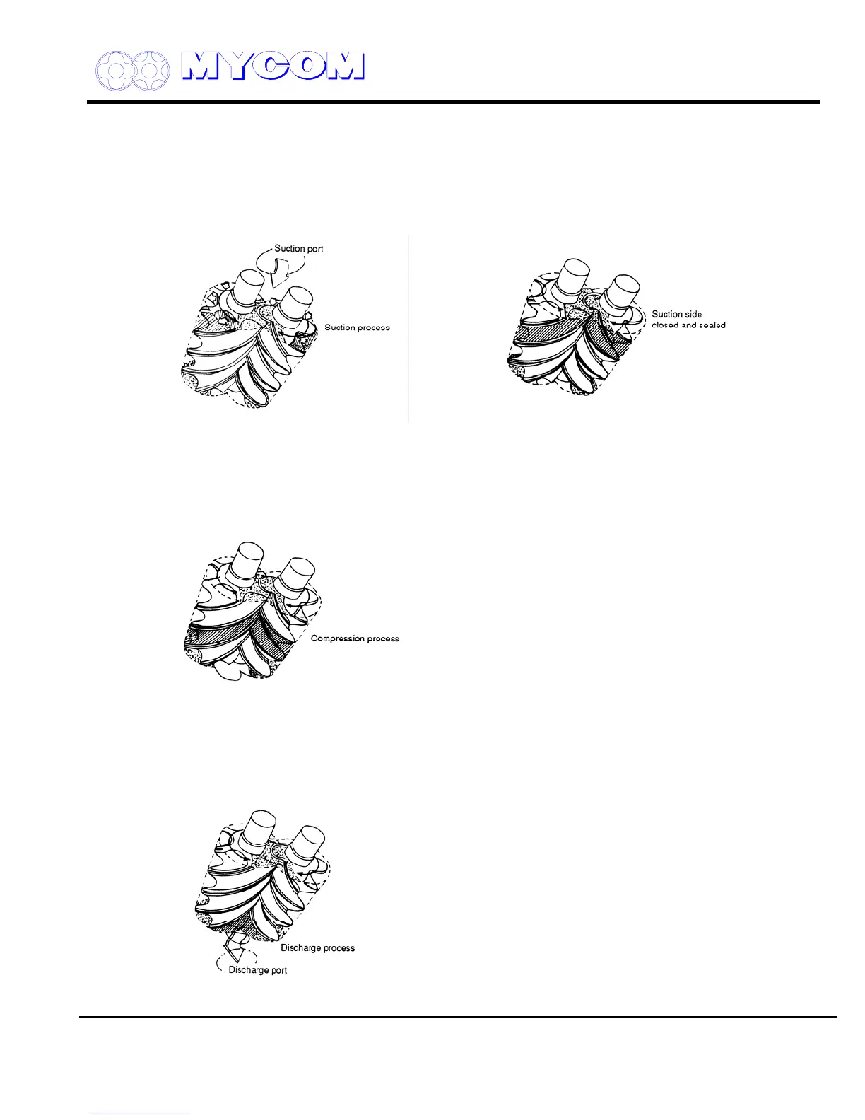
1.1.1 Suction Phase (refer to Figs. 4 and 5)
As shown in Fig. 4, the rotors of different lobe shape mate and the clearance between the M and F
rotors and the casing expands gradually from the suction side as the rotors rotate.
When the clearance reaches maximum as the rotors rotate further, it is sealed by the walls at both
ends of the rotor and becomes independent.
Fig. 4 Suction Phase Fig. 5 Suction Side Sealing
1.1.2 Compression Phase (refer to Fig. 6)
As the rotors further rotate, the suction side of the clearance is sealed by the mating of the lobes and
the volume between the lobes decreases while the sealing line moves toward the discharge side.
Fig. 6 Compression Phase
1.1.3 Discharge Phase (refer to Fig. 7)
When the volume is decreased to the designated Vi, the clearance between the discharge port and
the rotors is linked and the refrigerant is pushed to the discharge side.
Fig. 7 Discharge Phase
Supersedes all previous version. This information is for reference use only and subject to change without notice
Revision 2 (June 05,2000) Page 5 of 61

 Loading...
