REFRIGERATION DIVISION
V SERIES
SCREW COMPRESSOR HANDLING MANUAL
Supersedes all previous version. This information is for reference use only and subject to change without notice
Revision 2 (June 05,2000) Page 36 of 61
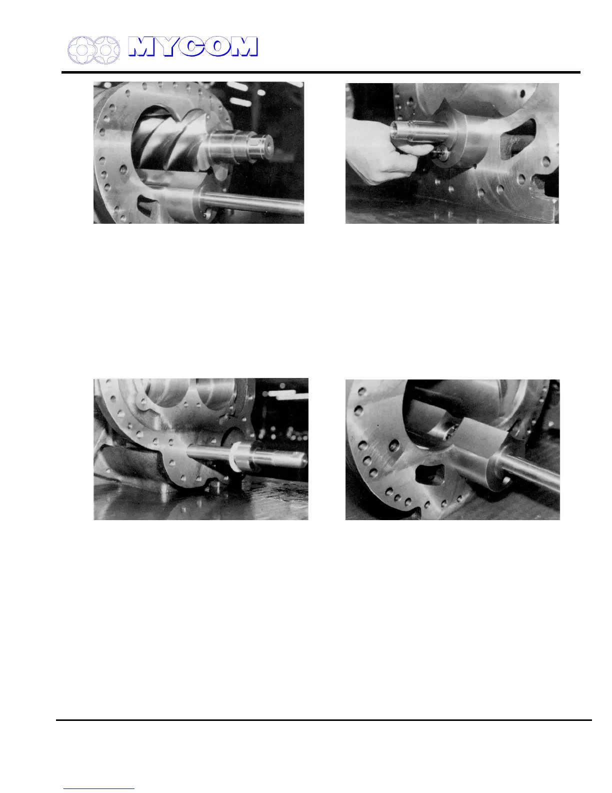
Fig. 61 Pulling out M rotor (25) Fig. 62 Removing Lock Washer Bolt
b) Remove the remaining rotor in the same manner, taking care not to damage the main bearing
in the bearing head as you pull the rotor free.
c) Do not lay the rotors directly on the floor or the edges of the lobes may be damaged. Rest the
rotor shaft ends on V-blocks.
d) Remove the hex-head socket cap screw (454) securing the lock washer (445) on the end of
the V
i
changing rod of the variable Vi slide valve (289) and remove the lock washer (445).
e) Turn the bearing side rod counterclockwise and draw the rod out. When the threaded portion
comes free, pull it out of the bearing head. Place the thrust washers (449) together to prevent
them from becoming lost.
Fig. 63 Pulling out Variable Vi Slide Valve Fig. 64 Pulling out Unloader Slide Valve (54)
Changing Rod (444) and Variable Vi Slide Valve (289)
f) Pull the unloader slide valve (54) and the variable Vi slide valve (289) out of the casing while
holding the unloader push rod.
By pulling on the variable Vi slide valve changing rod (444), the unloader slide valve (54) can
be separated.
3.4.10.2Inspection
a) Inspect the rotor journals for damage.
The shaft seal and bearing mounting portions must be inspected.
b) Inspect the rotor lobes, especially the edges, for damage or abnormal wear. If the compressor
has been operating normally, there should be no damage found. If, however, scoring or
scratches, etc. are found, it points to a problem with the suction strainer as such damage can
only be made by foreign matter entering the system.

 Loading...
