REFRIGERATION DIVISION
V SERIES
SCREW COMPRESSOR HANDLING MANUAL
Supersedes all previous version. This information is for reference use only and subject to change without notice
Revision 2 (June 05,2000) Page 40 of 61
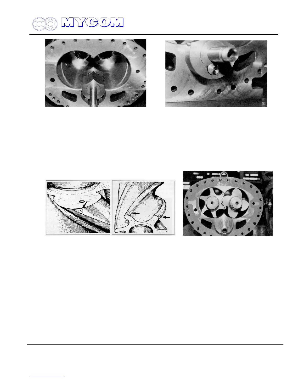
Fig. 75 Overall View of Unloader Slide Valve (54) Fig. 76 Fitting Vi Slide Valve Lock washer
(round) (445)
And Variable Vi Slide Valve
4.3 Rotor Casing (1) and Rotors (25,26)
a) Coat the main bearing and the shaft portion of the male rotor with compressor oil and install
first. Suspend the rotor from a rope or strap at its mid point and insert into the casing half way.
Release the rope or strap and push the rotor in fully.
b) The suction side leading edges of the female rotor stamped with the numbers “1” and “2”
should be oriented toward the male rotor side.
Fig. 77 Stamp Marks on Lobe Edges Fig. 78 Installing the Rotors
c) Lift the male rotor with the rope or strap. The number “1” stamped on the leading edge of one
lobe should be oriented toward the female rotor side.
d) Mate the rotors so that the leading edge of the male rotor lobe stamped with the number “1”
fits between the leading edges of the female rotor lobes stamped “1” and “2” and push the
female rotor in to half its length. Remove the belt suspending the female rotor and push it the
remainder of the way in. Proper orientation of the male and female rotor lobes is essential,
otherwise irregular lobe meshing will occur and the compressor will generate abnormal noise.
4.4. Suction Cover (5)
a) Fit the side bearing into the casing in the same manner as for the main bearing.
An O-ring (433) for the oil retainer is provided on the outer diameter. Be sure to install the O-
ring (433). If the cover must be tapped in, cushion with a plastic or wooden block and tap
around the positioning pin (8).

 Loading...
