REFRIGERATION DIVISION
V SERIES
SCREW COMPRESSOR HANDLING MANUAL
Supersedes all previous version. This information is for reference use only and subject to change without notice
Revision 2 (June 05,2000) Page 35 of 61
Fig. 58 O-Ring Gland (326)
d) Remove the O-ring gland fixing screw (456) and remove the O-ring gland (326).
e) To remove the side bearing (28), first remove the stop ring (29), and then push the side
bearing out from the rotor side. If a hammer must be used to free the bearing, cushion with a
wooden block or the like to prevent damage.
3.4.9.2 Inspection
a) Inspect the unloader push rod (67), O-ring (73) and suction cover side O-ring (9) for
deformation or other damage and replace with new ones if necessary.
b) Inspect the inner face of the side bearing (28) for foreign matter imbedded in the bearing
metal. Also, measure the dimensions of the bearing (ref. Service limits provided at the end of
this manual).
3.4.10 Rotors (25,26), Casing (1) and Variable V
i
Slide Valve (289)
The variable Vi slide valve and the unloader slide valve are mounted together in the rotor casing.
3.4.10.1Disassembly
a) As the screw compressor rotors are very heavy, a hemp rope or nylon belt should be made
available for use when the rotors are being removed. Suspend the rotor from the rope or belt
as it is clears the casing. Either the male or the female rotor may be removed first. When
removing the female rotor, rotate the rotor counterclockwise as you pull out. When the rotor is
approx. two-thirds of the way out, lift it slightly and pull it all out the way, suspended from the
rope or belt.
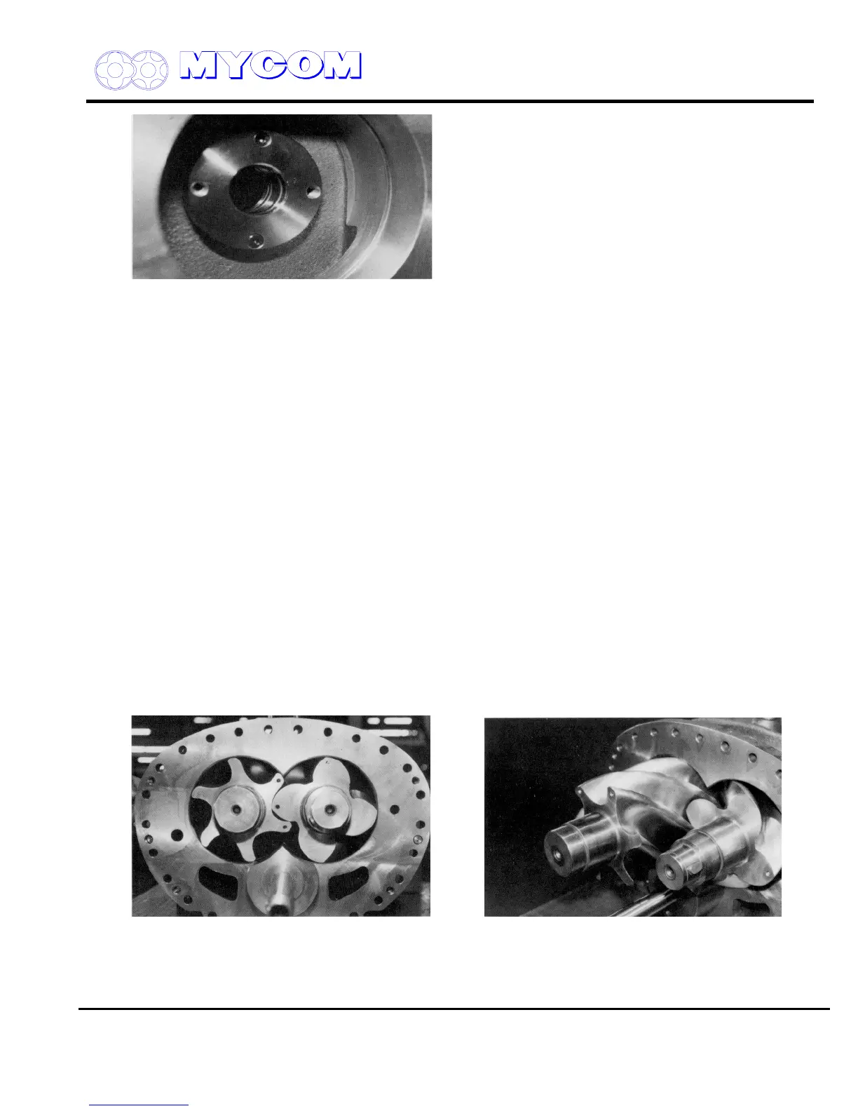
Fig. 59 Rotors (25, 26) Fig. 60 Pulling out Rotors

 Loading...
