REFRIGERATION DIVISION
V SERIES
SCREW COMPRESSOR HANDLING MANUAL
Supersedes all previous version. This information is for reference use only and subject to change without notice
Revision 2 (June 05,2000) Page 33 of 61
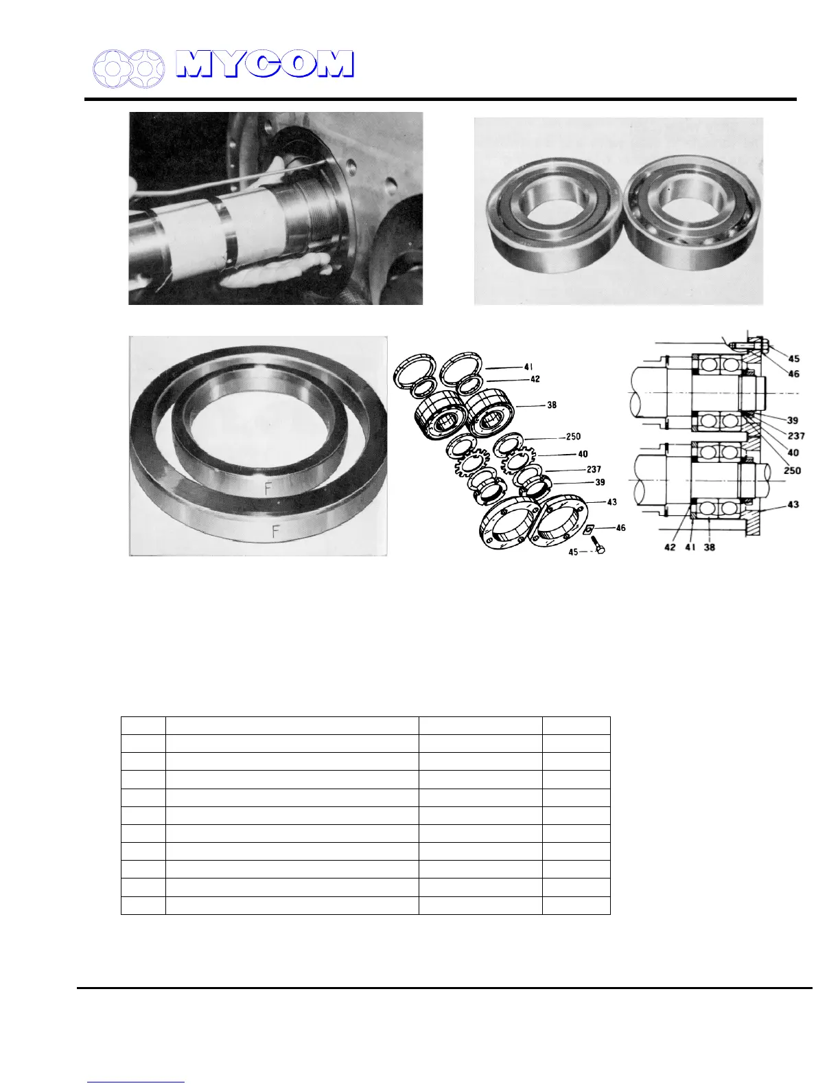
Fig. 53 Drawing out Thrust Bearing Fig. 54 Set of Thrust Bearing (L side lies on R side)
Fig. 55 Stamps on Thrust Bearing Gland Fig. 56 Thrust Bearing Portion of models 160V**~200V**
(step) (41) and Thrust Adjusting Washer (42)
d) The thrust adjusting washer (42) and thrust bearing step (41) are provided behind the thrust
bearing (some models do not have this arrangement for structural reasons).
Parts are stamped to indicate those for the Male (M) rotor and those for the Female (F) rotor.
Keep related parts together and do not mix. Improper assembly will cause dimensional errors
and compressor seizure (refer to Fig. 55).
No. Name 160V**~200V** 250V**
38 Thrust Bearing 2 sets 2 sets
39 Lock Nut 2 pcs. 2 pcs.
40 Lock Washer 2 pcs. 2 pcs.
41 Thrust Bearing Step 2 pcs. ʊʊ
42 Thrust Bearing Adjusting Washer 2 pcs. 2 pcs.
43 Thrust Bearing Tightening Washer 2 pcs. 2 pcs.
45 Hex-Head Bolt 8 pcs. 8 pcs.
46 Hex-Head Bolt Lock Washer 8 pcs. 8 pcs.
237 Thrust Lining Plate 2 pcs. 2 pcs.
250 Thrust Bearing Washer 2 pcs. 2 pcs.

 Loading...
