REFRIGERATION DIVISION
V SERIES
SCREW COMPRESSOR HANDLING MANUAL
Supersedes all previous version. This information is for reference use only and subject to change without notice
Revision 2 (June 05,2000) Page 39 of 61
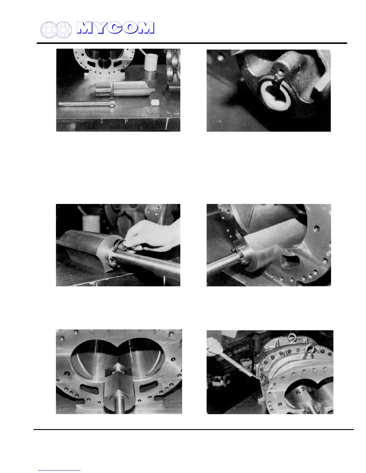
Fig. 69 View of Unloader Slide Valve (54), Fig. 70 Unloader Slide Valve (54) and portion
Variable Vi Slide Valve (289) and Vi changing
Rod (444) Removed from Rotor Casing (1)
d) Mount the Vi changing rod (444) from the bearing head side. Be careful not to forget to install
the thrust washer (449).
Push the unloader slide valve (54) to the discharge side and fit the female screw of the
variable Vi slide valve on the Vi changing rod.
When the end of the Vi changing rod extends from the Vi slide valve, secure the lock washer.
Fig. 71 O-Ring for Vi Changing Rod (451) of Fig. 72 Mounting Unloader Slide Valve (54)
Unloader Slide Valve (54)
e) If the gasket on the bearing head protrudes into the rotor casing, trim the excess gasket
material away. If the gasket is caught between the end face of the rotor and the bearing head,
thrust clearance cannot be adjusted properly.
Fig. 73 Mounting Variable Vi Slide Valve (289) Fig. 74 Mounting Bearing Head (11) and Rotor Casing

 Loading...
