REFRIGERATION DIVISION
V SERIES
SCREW COMPRESSOR HANDLING MANUAL
1.1 Refrigerant Compression Mechanism
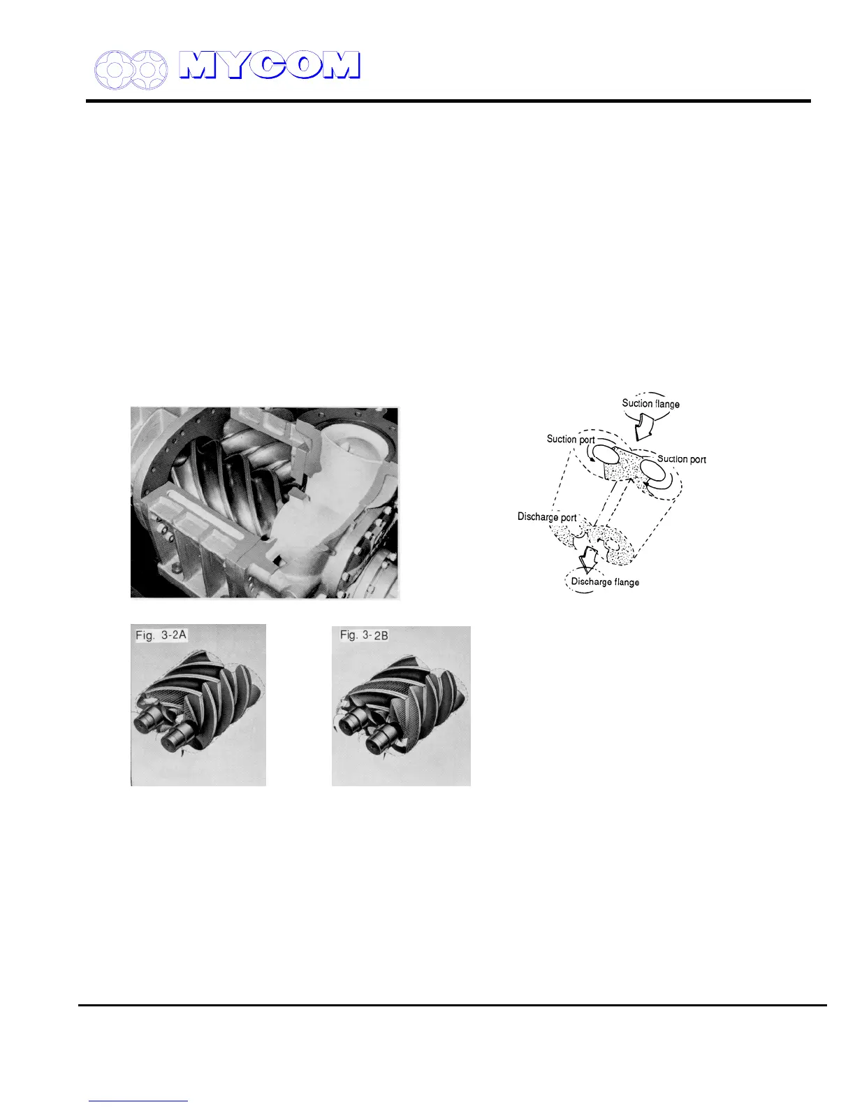
As shown in Figs. 1 and 2, a pair of mated helical gears, or rotors, are mounted in the compressor
casing. The rotor having the four-lobe section is called the male (M) rotor while the one with the six-
lobe section is called the female (F) rotor.
A two-pole motor connected directly to the M rotor drives the compressor at speeds of 2,950 rpm or
3,550 rpm (50 Hz or 60 Hz)
Compressor efficiency is directly related to the shape of the rotor lobes. In the case of the V-Series,
the rotors have unsymmetrical profiles in contrast to conventional screw compressor rotor lobes. This
unsymmetrical design reduces the triangular blow off hole between the casing and the rotors to 60%,
minimizing leakage due to the pressure difference.
Normally, an oil film seals the clearance between the leading edges of the rotor lobes and the casing.
With the V-Series, however, a change has been incorporated to raise the pressure of the oil film and
the clearance between the casing and the lobe leading edges is wedge shaped.
Fig. 2 Screw Compressor cross sectional view Fig. 3 Rotor Rotation & the Compression Cycle
Supersedes all previous version. This information is for reference use only and subject to change without notice
Revision 2 (June 05,2000) Page 4 of 61

 Loading...
