Wiring
FP0
7-8
Matsushita Automation Controls
7.4 Input Wiring
7.4 Input Wiring
.
Notes
D
Be sure to select the thickness (dia.) of the input wires while
taking into consideration the required current capacity.
D
Arrange the wiring so that the input and output wiring are
separated, and so that the input wiring is separated from the
power wiring, as much as possible. Do not route them through
the same duct or wrap them up together.
D
Separate the input wires from the power and high voltage
wires by at least 100 mm/3.937 in.
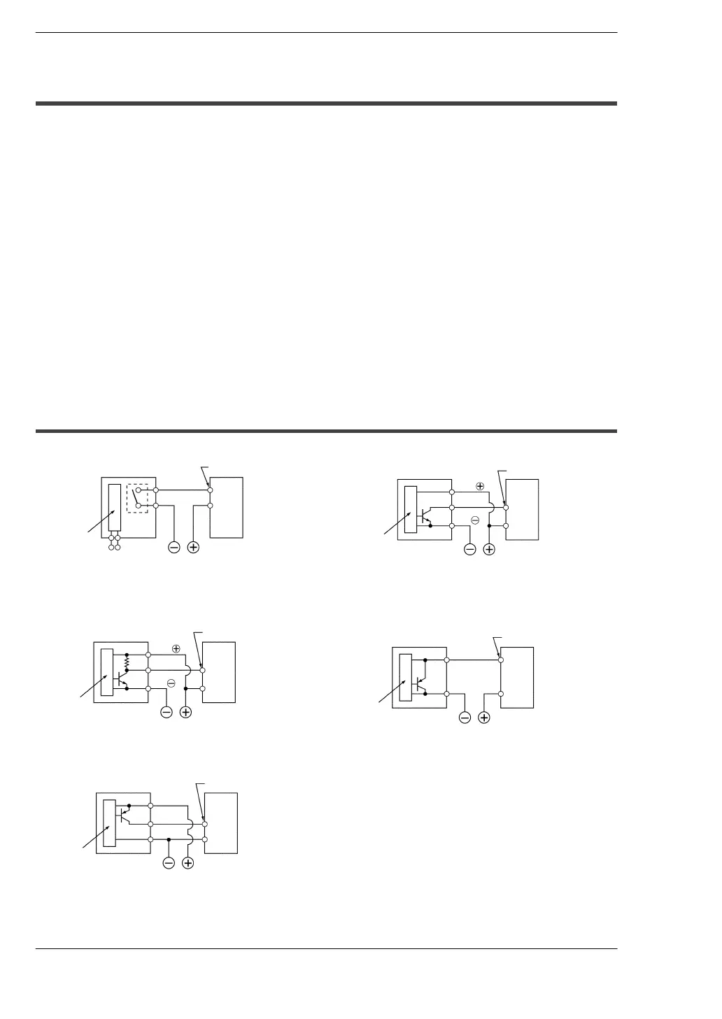
In this section you find some examples for wiring sensors, an LED-equipped reed
switch, a two-wire type sensor and a LED-equipped limit switch.
7.4.1 Sensors
Relay output type NPN open collector output type
FP0
Power supply
for sensor
Relay
COM
Input terminal
Sensor
Internal
circuit
Power supply
for input
FP0
Output
0V
COM
Input terminal
Sensor
Power supply for input
Internal
circuit
Vcc
Universal output type Two-wire type (
*
next page)
FP0
Output
0V
FP0
COM
Input terminal
Sensor
Power supply for input
Internal
circuit
Vcc
COM
Input terminal
Sensor
Power supply for input
Internal
circuit
PNP open collector output type
FP0
COM
Input terminal
Sensor
Power supply for input
Internal
circuit
 Loading...
