Analog I/O Unit
FP0
4-14
Matsushita Automation Controls
4.5 Wiring
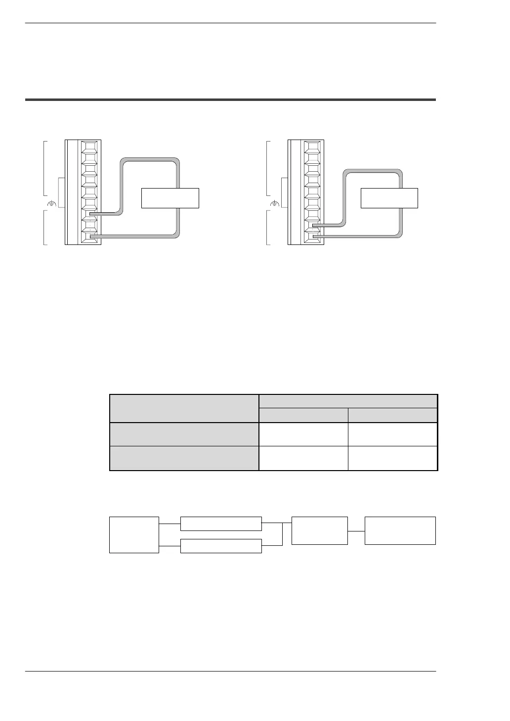
4.5.2 Analog Output Wiring
V0
I0
V1
I1
COM
V
I
COM
IN
OUT
Connect output instrument between OUT/I
and OUT/COM terminal.
Voltage output
Output
instrument
Connect output instrument between OUT/V
and OUT/COM terminal.
Current output
V0
I0
V1
I1
COM
V
I
COM
IN
OUT
Output
instrument
.
Notes
D Always make sure the switch settings and the terminal base wiring
connections match. For output, in particular, if the settings and the
wiring connections are wrong, the control unit will output values like
those shown below, even in the PROG. mode. (For information on
switch settings, see
*
section 4.1.1.)
Item
Output terminal (OUT)
Current terminal (I) Voltage terminal (V)
0 mA output based on current
range setting
0mA -10 V
0 V output based on voltage
range setting
10 mA 0V
D DA internal block diagram
A voltage amplifier and current amplifier are connected in parallel
to a single DA converter IC.
Terminal
DA converter
Microcomputer
Voltage amplifier
Current amplifier
Also, the digital value that is sent to the DA converter IC to achieve
a voltage output of 0 V is different from that input to the DA
converter IC to achieve a current output of 0 mA.
As a result, if the voltage output is set to 0 V, 10 mA is output from
the current output terminal, and conversely, if the current output is
set to 0 mA, - 10 V is output from the voltage output terminal (see
tables the next page).
.
next page
 Loading...
