Control Units
FP0
2-14
Matsushita Automation Controls
2.2 Specifications
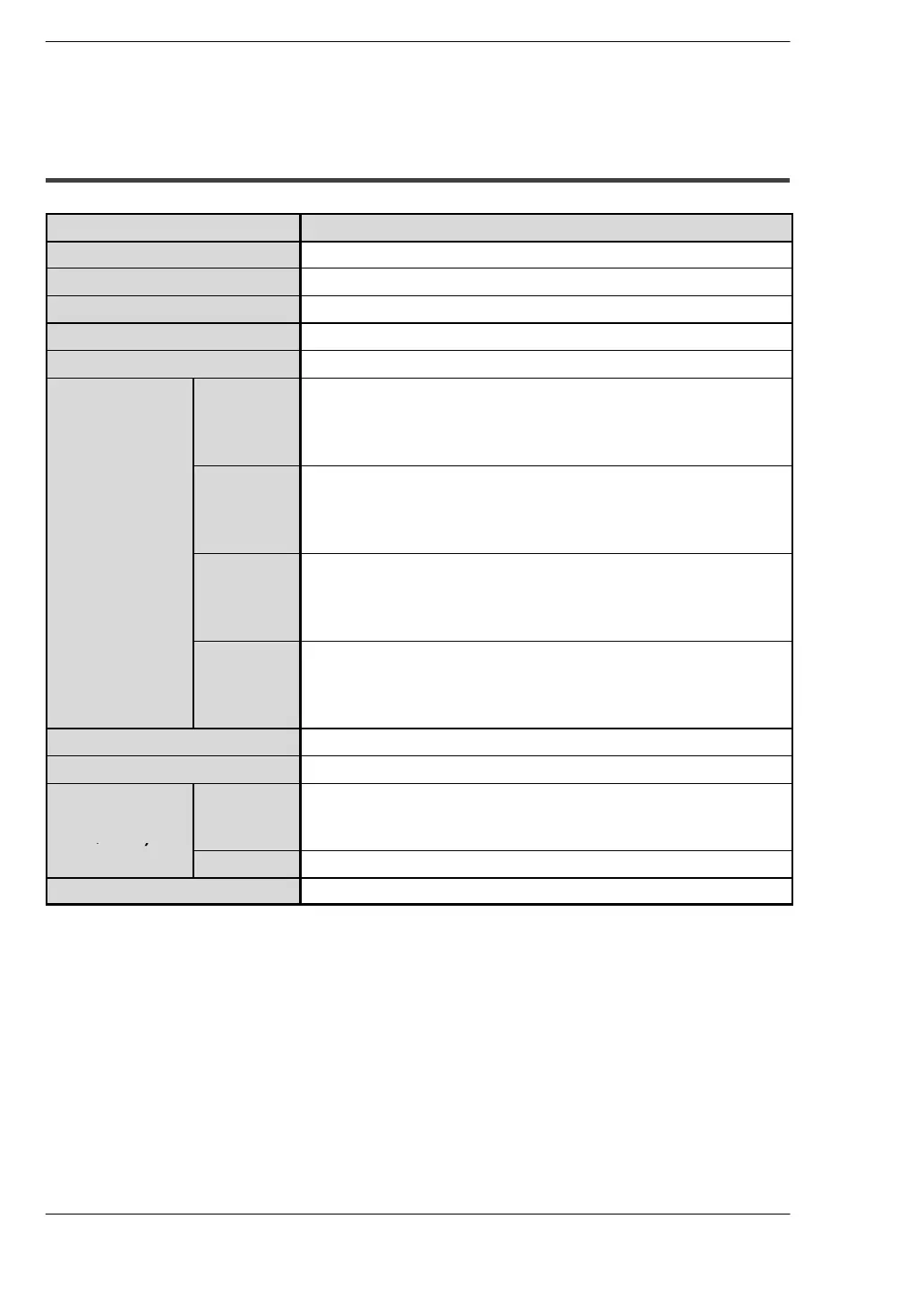
2.2.3 Input Specifications
Item Description
Insulation method
optical coupler
Rated input voltage
24 V DC
Rated input current
approx. 4.3 mA (at 24 V DC)
Input impedance
approx. 5.6 k
Ω
Operating voltage range
21.6 to 26.4 V DC
Input points
per common
(
*
Note 1)
C10RM,
C10CRM,
C10RS,
C10CRS
6 points/common
C14RM,
C14CRM,
C14RS,
C14CRS
8 points/common
C16T,
C16CT,
C16P,
C16CP
8 points/common
C32T,
C32CT,
C32P,
C32CP
16 points/common
ON voltage/ON current
19.2 V or less/3 mA or less
OFF voltage/OFF current
2.4 V or more/1 mA or more
Response time
(at 24 V DC and
25
q
C/66
q
F)
OFF
l
ON
50
μ
s or less (at X0, X1) (
*
Note 2)
100
μ
s or less (at X2 to X5) (
*
Note 2)
2 ms or less (at X6 to XF)
ON
l
OFF
the same as above
Operating mode indicator
LED
.
Notes
D
(
*
1): Either positive or negative polarity is possible for the input
voltage supply.
D
(
*
2): X0 through X5 are inputs for the high-speed counter and
have a fast response time. If used as normal inputs, we
recommend inserting a timer in the ladder program as
chattering and noise may be interpreted as an input signal.
 Loading...
