Connecting the I.O.P. Display Panel
FP0
8-4
Matsushita Automation Controls
8.1 Connecting the I.O.P. D01/D30/M01/M30
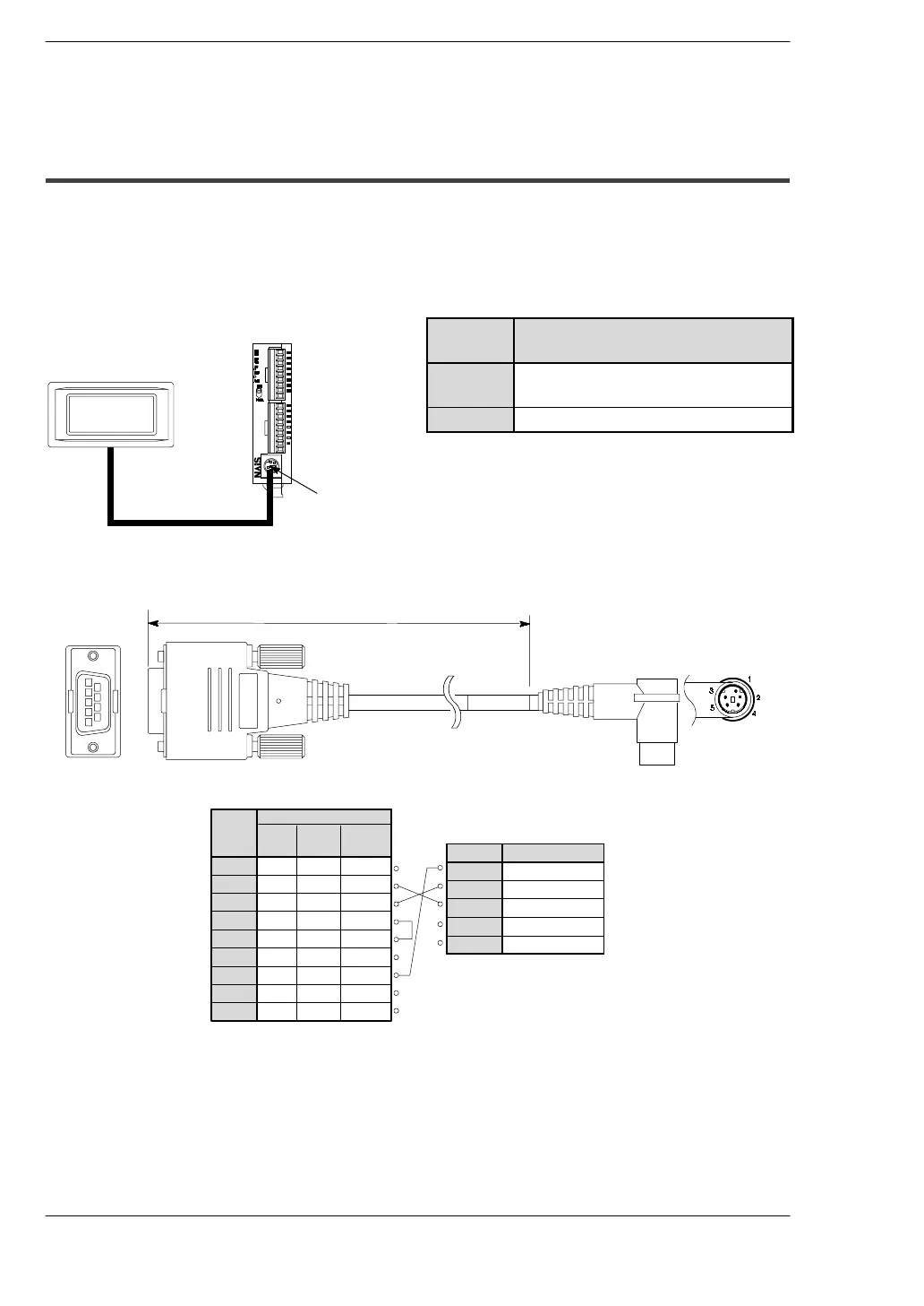
8.1.2 Connection Using the Tool Port
It is possible to input data and output data with an external device (I.O.P.
D01/D30/M01/M30) using the tool port.
When connecting to the I.O.P., set the system registers 411 and 414 according to the
following chart. For more complete details, refer to the
*
FP0 Programming Manual.
System
register
Setting
411
Modem communication: Enabled
Character bits: 8 bits
414
Baud rate: 19,200 bps
Serial communication cable (order number: AIP81862M)
2 m/6.56 ft.
1
2
3
4
5
6
7
8
9
Pin no. Abbreviation
SG
1
SD
2
RD
3
N.C.
4
5
+5V
FP0
(Tool port)
Pin no. Abbreviation
N.C.
SD
RD
RS
CS
SG
SG
N.C.
N.C.
I.O.P.
1
2
3
4
5
6
7
8
9
D30 M30
D01
M01
N.C.
SD
RD
RS
CS
N.C.
SG
N.C.
ER
N.C.
SD
RD
RS
CS
N.C.
SG
N.C.
N.C.
Serial communication cable
I.O.P. D01
Tool port
FP0 control unit
 Loading...
