Connecting the I.O.P. Display Panel
FP0
8-6
Matsushita Automation Controls
8.2 Connecting the I.O.P. B01/B30
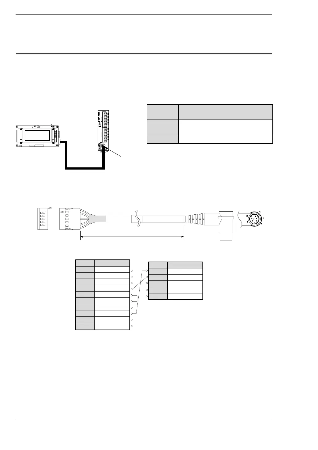
8.2.2 Connection Using the Tool Port
It is possible to input data and output data with an external device (I.O.P. B01/B30) using
the tool port.
When connecting to the I.O.P., set the system registers 411 and 414 according to the
following chart. For more complete details, refer to the
*
FP0 Programming Manual.
System
register
Setting
411
Modem communication: Enabled
Character bits: 8 bits
414
Baud rate: 19,200 bps
Serial communication cable (order number: AIB81222)
Pin no. Abbreviation
1
N.C.
2
3
SD
4
RD
5
CS
6
RS
7
SG
8
SG
9
+5V
Pin no. Abbreviation
SG
1
SD
2
RD
3
N.C.
4
5
I.O.P.
FP0
(Tool port)
10
1
3
5
7
9
2
4
6
8
10
2m/ 6.56 ft
+5V
+5V
N.C.
I.O.P. B01
Serial communication cable
Tool port
FP0 control unit
 Loading...
