Analog I/O Unit
FP0
4-7
Matsushita Automation Controls
4.2 Specifications
.
Notes
D
(
*
1): The temperature lower than the temperature of terminal of
the analog I/O unit cannot be measured.
D
(
*
2): The temperature higher than the temperature of terminal of
the analog I/O unit cannot be measured.
D
(
*
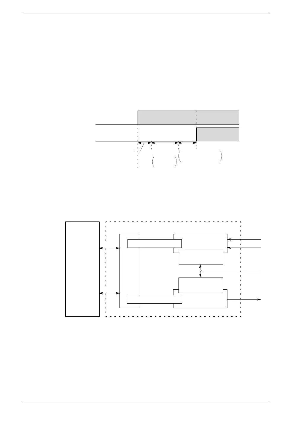
3): The time noted below is required before the analog data is
reflected in the control unit input.
0msto
scan time
1ms
×
number
of expansion units
0V
10V
K0
K2000
Conversion
time: (1 ms)
Refresh
standby
Refresh
Analog input
WX2
D
(
*
4): Refer to the
*
section 4.6 “Boosting the Precision of the
Thermocouple Range.”
D
(
*
5): Refer to the schematic diagram of insulation methods
below.
FP0 Control
unit
I/F
Photocoupler insulation Analog input
Analogoutput
Analog I/O unit
DC/DC converter
insulation
CH0
24 V DC
+5V
Bus
CH1
DC/DC conv erter
insulation
Photocoupler insulation
D
(
*
6): The number for the input contact point being used varies
depending on the expansion location (
*
section 5.4).
 Loading...
