Connecting the I.O.P. Display PanelFP0
8-3Matsushita Automation Controls
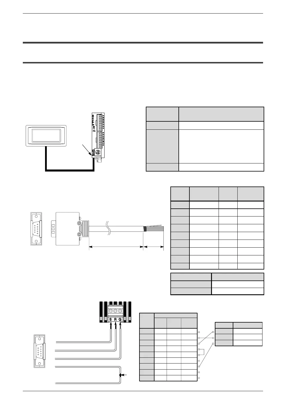
8.1 Connecting the I.O.P. D01/D30/M01/M30
8.1 Connecting the I.O.P. D01/D30/M01/M30
8.1.1 Connection Using the RS232C Port
It is possible to input data and output data with an external device (I.O.P.
D01/D30/M01/M30) using the RS232C port.
When connecting to the I.O.P., set the system registers 412 to 414 according to the
following chart. For more complete details, refer to the
*
FP0 Programming Manual.
System
register
Setting
412
K1 (Computer Link)
413
Header: without STX code
Terminator: CR
Stop bit: 1 bit
Parity check: Odd
Character bits: 8 bits
414
Baud rate: 19,200 bps
Pin no. Abbreviation
Wire
color
Dotted
line color
1
N.C. Orange Red
2
SD Orange Blue
3
RD Gray Red
4
RS Gray Blue
5
CS White Red
6
N.C.
— —
7
SG White
Blue
8
N.C.
— —
9
N.C.
— —
Length Order number
1 m/3.28 ft
AIP81841
2 m/6.56 ft
AIP81842
I.O.P. D01
Serial communication cable
RS232C
port
FP0 control unit
Length
50 mm/1.97 in.
Serial communication cable
6
7
8
9
1
2
3
4
5
Pin no. 3 (Wire: Gray/Dotted:Red)
Pin no. 2 (Wire: Orange/ Dotted: Blue)
Pin no. 7 (Wire: White/Dotted:Blue)
Pin no. 5 (Wire:White/Dotted: Red)
Pin no. 4 (Wire: Gray/Dotted: Blue)
Short
circuit
FP0
(RS232C port)
Pin no. Abbreviation
N.C.
SD
RD
RS
CS
SG
SG
N.C.
N.C.
Pin no. Abbreviation
S
SD
R
RD
G
SG
FP0
(RS232C port)
I.O.P.
1
2
3
4
5
6
7
8
9
D30 M30
D01
M01
N.C.
SD
RD
RS
CS
N.C.
SG
N.C.
ER
N.C.
SD
RD
RS
CS
N.C.
SG
N.C.
N.C.
6
7
8
9
1
2
3
4
5
I.O.P.
 Loading...
