Wiring
FP0
7-10
Matsushita Automation Controls
7.4 Input Wiring
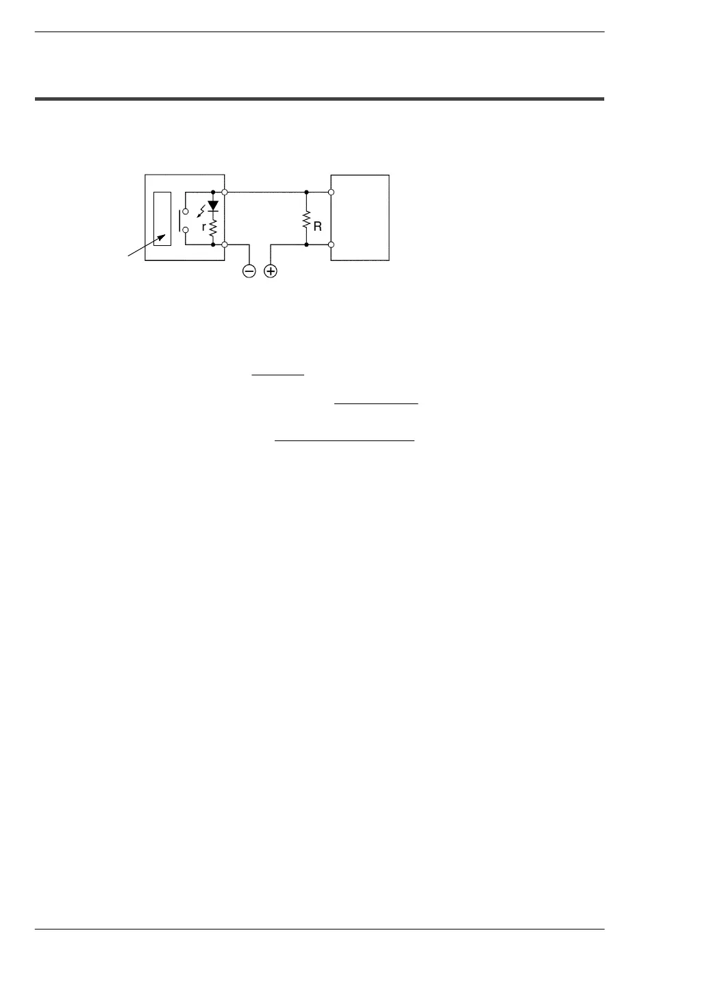
7.4.4 LED-Equipped Limit Switch
If the input of the FP0 does not turn OFF because of the leakage current from the
LED-equipped limit switch, the use of a bleeder resistor is recommended, as shown
below.
FP0
Internal circuit
r: Internal resistor of limit switch (k
Ω
)
R: Bleeder resistor (k
Ω
)
The OFF voltage of the FP0 input is 2.4 V, therefore when the power supply voltage is 24 V,
select R so that
the current will be greater than I =
The resistance R of the bleeder resistor is: R
≦
The wattage W of the resistor is: W =
In the actual selection, use a value that is 3 to 5 times the value of W.
13.44
5.6
×
I
- 2.4
(k
:
)
24 - 2.4
r
(Power supply voltage)
2
R
LED-equipped
limit switch
COM
Input
terminal
Bleeder
resistor
 Loading...
