Expansion I/O Units
FP0
3-16
Matsushita Automation Controls
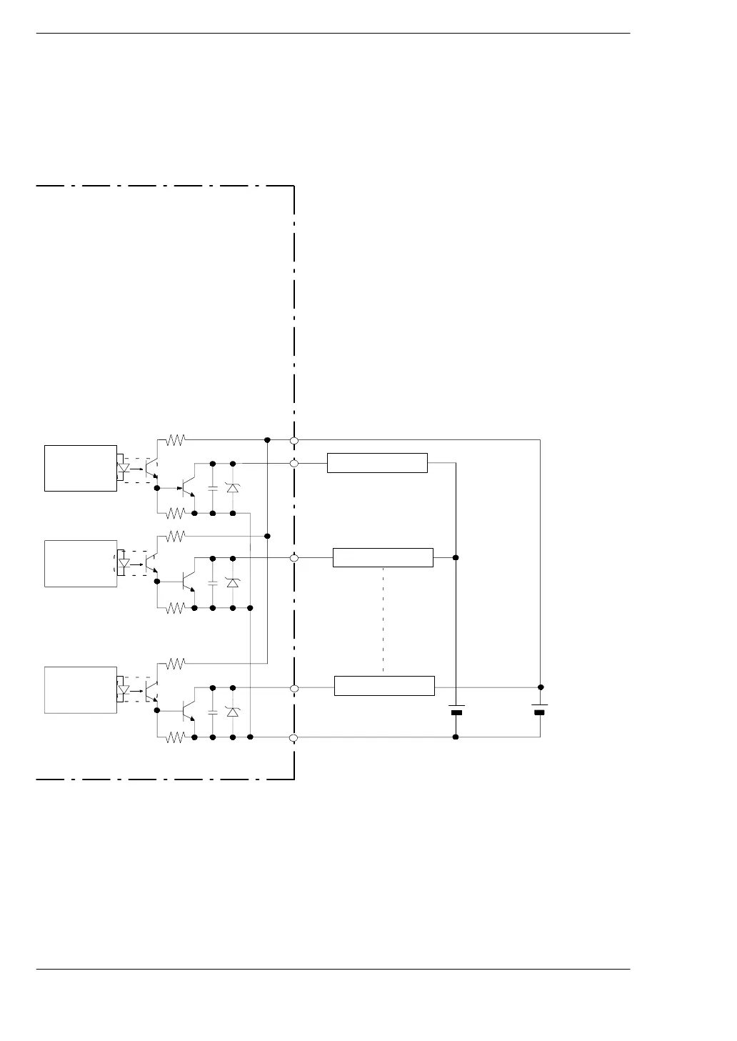
3.3 Internal Circuit Diagram
When the load voltage differs from the 24 V DC external power supply for the
driving the internal circuit
Other than 24 V DC load voltage, 5 V DC and 12 V DC and other load voltages can be
connected.
FP0-E8YT/E16YT
Y20
(+)
Y21
(-)
Y2n
24 V DC
(External
power supply
for driving
internal circuit)
5V DC
(Rated load
voltage)
Internal circuit
Internal circuit
Internal circuit
Load (for 24 V DC)
Load (for 5 V )
Load (for 5 V )
Output side
.
Note
The output number given above is the output number when the
expansion output unit is installed as the first expansion unit
(
*
section 5.3).
 Loading...
